

Method and apparatus for machining a surgical implant
a surgical implant and machining technology, applied in the direction of joint implants, manufacturing tools, prosthesis, etc., can solve the problem of unacceptable long turn around time for custom bio-implants based on allograft bone, and achieve the effect of adjusting the overall mechanical properties of the osteo-implan
- Summary
- Abstract
- Description
- Claims
- Application Information
AI Technical Summary
Benefits of technology
Problems solved by technology
Method used
Image

Examples
Embodiment Construction
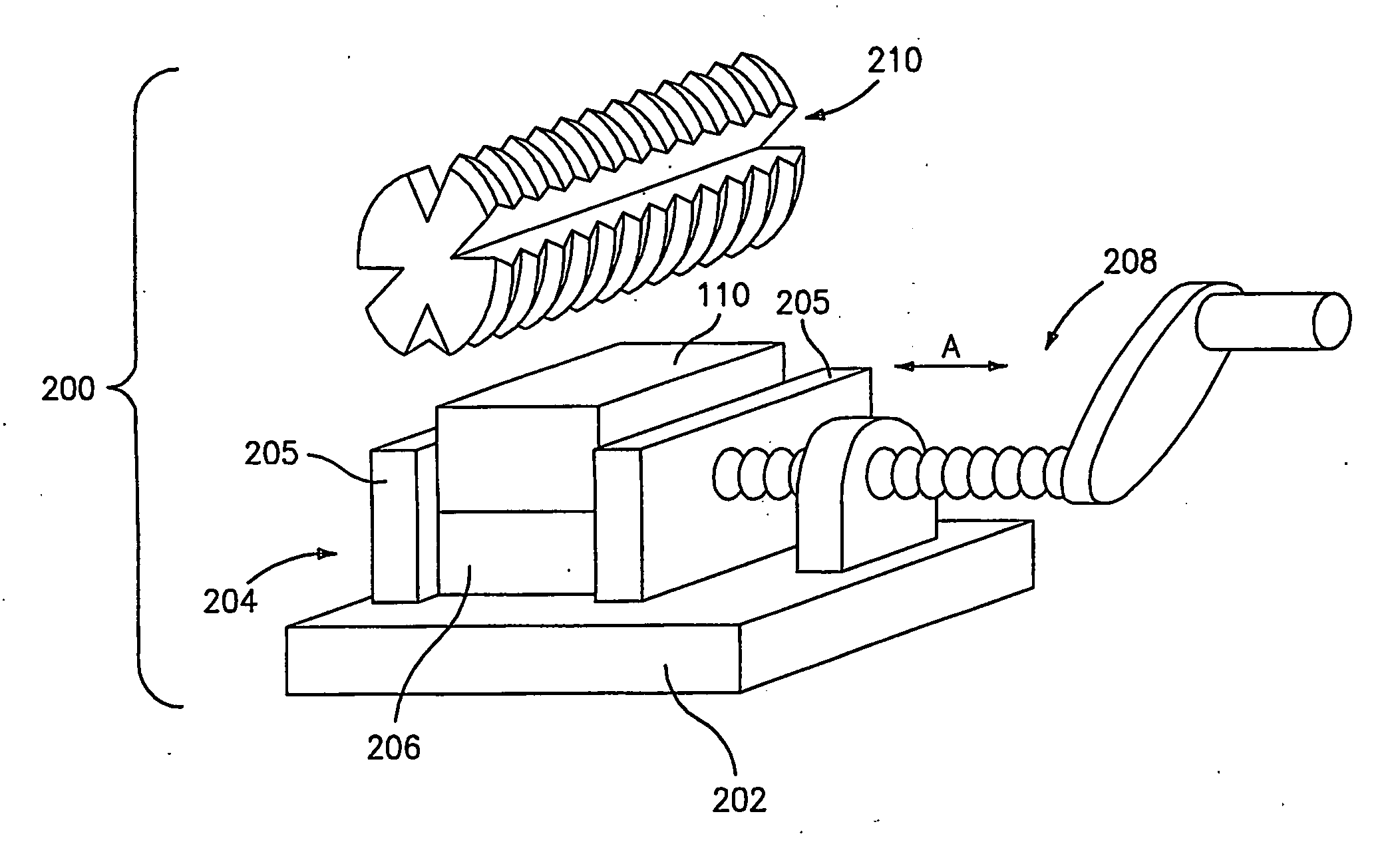
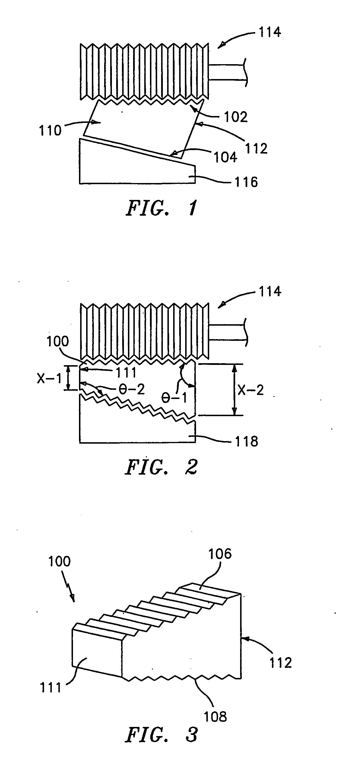
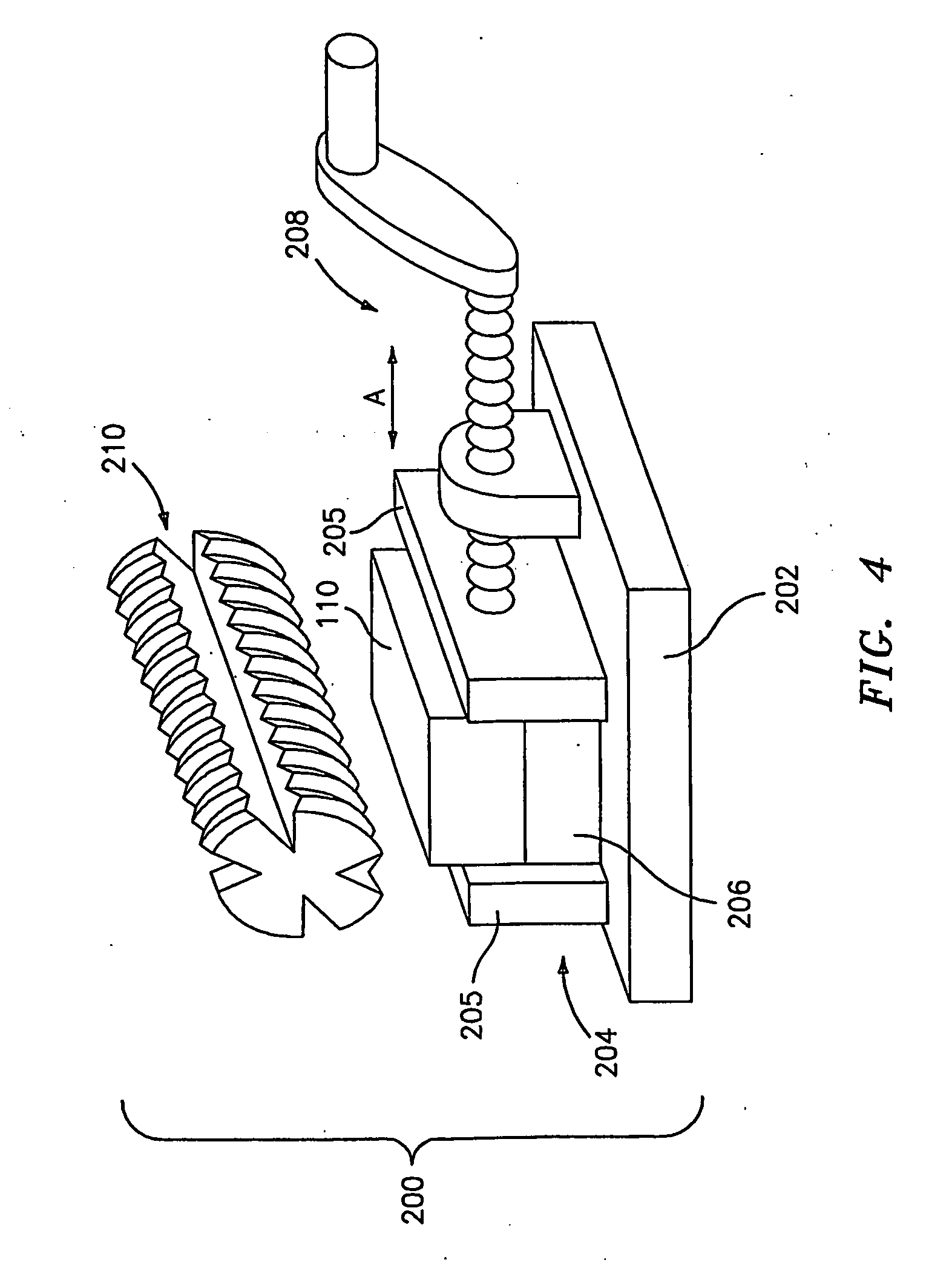
[0045] The present invention is directed to methods and apparatus for machining a bone blank intra-operatively in the operating room to produce a customized surgical bio-implant.
[0046] Bone blanks which can be machined in accordance with the present invention include those made of monolithic bone, or bone composites made from pieces of bone, bone particles, etc. The bone component of the bone blanks can be mineralized, demineralized, partially demineralized and combinations thereof. Such composites are disclosed, for example, in U.S. Pat. Nos. 6,478,825, 6,440,444, 6,294,187, 6,294,041 and 6,123,731, the contents of each of which are incorporated by reference herein. The bone blank, especially where it is made of a composite or aggregate of bone particles, can be combined with one or more biocompatible components such as wetting agents, biocompatible binders, fillers, fibers, plasticizers, biostatic / biocidal agents, surface active agents, bioactive agents, and the like, prior to, d...
PUM
| Property | Measurement | Unit |
|---|---|---|
| Angle | aaaaa | aaaaa |
| Heat | aaaaa | aaaaa |
Abstract
Description
Claims
Application Information