Dental laser treatment device

a laser treatment and laser technology, applied in the field of dental laser treatment devices, can solve the problems of user body heat, insufficient cooling of healthy tooth tissue surrounding the treatment area, and time-consuming input of parameters before each treatment, so as to reduce radiation of the hand grip sleeve, and improve the protection against soiling and damage.

Inactive Publication Date: 2005-11-03
W&H DENTALWERK
View PDF14 Cites 41 Cited by
  • Summary
  • Abstract
  • Description
  • Claims
  • Application Information

AI Technical Summary

Benefits of technology

[0008] In a first embodiment the temperature sensor is fitted to the outside of the handpiece, preferably on the outer perimeter of the distal end of the handpiece in the immediate vicinity of the orifice for emitting the laser beam. In accordance with a second preferred embodiment, the temperature sensor is located inside the handpiece, in particular in the optical path of the laser light or inside the coupling, allowing better protection from soiling and damage.
[0009] If the temperature sensor is located inside part of the handpiece / coupling in particular, which is held in the hand by the user for a prolonged period, there is a danger of the body heat of the user warming the hand grip sleeve and the radiation of the hand grip sleeve subsequently influencing and falsifying the measurement of the heat radiation. The handpiece and / or the coupling is therefore preferably equipped with an inner sleeve located inside the hand grip sleeve and connected to fixed components within the handpiece. A gap between the hand grip and the inner sleeve serves as an insulator. In addition, the gap between the two sleeves can be connected to a rotor wheel, preferably located in the control unit, which forces cooling air into the gap by means of a supply tube. The heat is convectively transported from the handpiece with the cooling air by means of an opening in the proximal area of the handpiece / coupling or via a return air line in the supply tube and the radiation of the hand grip sleeve thus reduced.
[0010] Additional protection from the radiation of the hand grip sleeve is achieved by casing the temperature sensor, preferably in a metallic encapsulation, with a window of zinc selenide or germanium to allow passage of the heat radiation and a bore for the signal wire, sealed from the interior of the handpiece by a seal, preferably an O-ring. This also protects the temperature sensor from direct contact with vapours or chemicals during cleaning or disinfection.

Problems solved by technology

Despite the use of cooling media, in particular cooling liquids or cooling air, sufficient cooling of the healthy tooth tissue surrounding the treatment area is not fully guaranteed.
The disadvantage of this device is that determination of the tooth temperature is performed solely by means of the calculations carried out by the control unit, based in part on the values entered before treatment commences, and therefore does not reflect the actual treatment situation at the tooth.
Moreover, the input of parameters before each treatment is time-consuming for the user.
If the temperature sensor is located inside part of the handpiece / coupling in particular, which is held in the hand by the user for a prolonged period, there is a danger of the body heat of the user warming the hand grip sleeve and the radiation of the hand grip sleeve subsequently influencing and falsifying the measurement of the heat radiation.

Method used


Image

  • Dental laser treatment device
  • Dental laser treatment device
  • Dental laser treatment device

Examples


Embodiment Construction

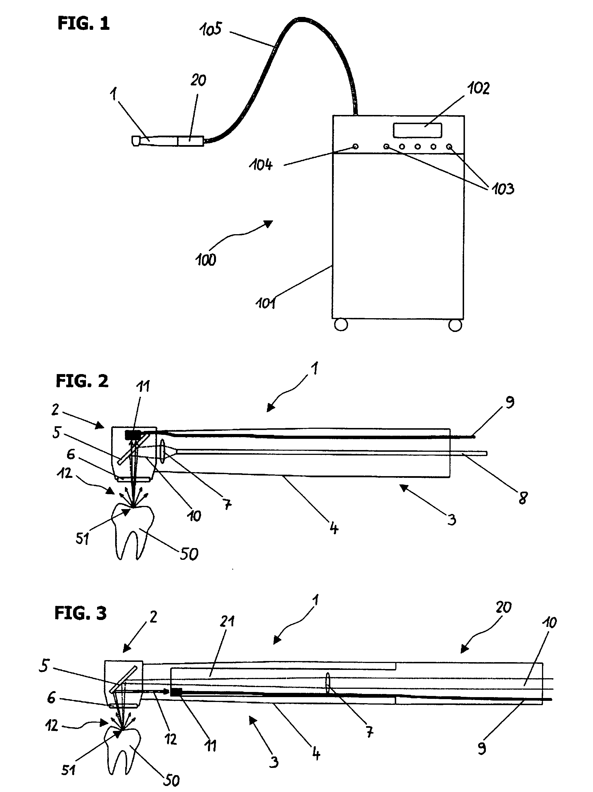
[0037] The invented device 100 for emitting a laser beam for dental treatment in accordance with FIG. 1 consists of a casing 101, containing the laser source and a control device with evaluation and control electronics, preferably as part of a microprocessor. The electronics serve as open and closed loop controls for the operating parameters, for example the power output of the laser source or volume control of the cooling media water and air, and for processing the signals from the sensors, which are connected to the handpiece 1 or the coupling 20. On the display 102, which is connected to the electronics, the user can read off operating data and select programmes or alter parameters with the help of a numbers of push buttons 103. Via an interface 104 the evaluation and control electronics are connected to a printer for output of the operating settings and treatment parameters. Preset operating programs and editable settings and parameters are stored in one or more memories connect...


PUM


Abstract

Described are a handpiece, a coupling, and a device with a laser source and handpiece for emitting a laser beam for dental treatment. In order to avoid damage to the healthy tooth tissue, an improved determination of the tooth temperature by measurement of at least part of the heat radiation emitted from the treatment area using a temperature sensor, preferably an infra-red sensor, is carried out. Upon reaching or exceeding a temperature threshold, the emission of the laser beam to the treatment area is interrupted or the power output of the laser source reduced or the user made aware of the violation of the threshold value using an acoustic or visual signal. The temperature sensor can be located, e.g., on the handpiece or on the coupling, such as on the coupling tube.

Description

CROSS-REFERENCE TO RELATED APPLICATION [0001] The present application claims priority from pending Austrian Patent Application No. A 730 / 2004, filed Apr. 28, 2004, which is incorporated herein by reference. FIELD [0002] The present invention relates to a handpiece, a coupling and a device with a laser source and handpiece for emitting a laser beam for dental treatment. DESCRIPTION OF PRIOR ART [0003] The aim of every therapeutic or diagnostic treatment is, beside the treatment of actual medical problems, to avoid side effects such as injuries to healthy tissue. In the case of dental treatment using laser beams the tooth is subject to heat caused by energy transfer, whereby healthy tooth material adjoining the carious regions, and the tooth pulp with its associated nerve endings in particular, is affected. If inflammatory processes occur, pain attacks can be initiated at pulp temperatures as low as 37° C. and irreversible damage be caused by long-term thermal stressing up to and incl...

Claims


Application Information

Patent Timeline
Patent Type & Authority Applications(United States)
IPC IPC(8): A61C1/00
CPCA61C1/0046
Inventor STRASSL, MARTINKASENBACHER, ANTON
Owner W&H DENTALWERK
Why Eureka
Try Eureka