Disc shunt for treating back pain

a disc shunt and back pain technology, applied in the field of disc shunt for treating back pain, can solve the problems of reducing the production of lactic acid in the anaerobic environment with the presence of lactic acid, and achieve the effect of preventing excessive plugging

Inactive Publication Date: 2005-11-03
YEUNG JEFFREY E
View PDF1 Cites 100 Cited by
  • Summary
  • Abstract
  • Description
  • Claims
  • Application Information

AI Technical Summary

Benefits of technology

[0014] In the supine position, the pressure within the shunted disc is low. Nutrients and oxygen from the vertebral body are transported through the conduit into the deprived cells within the, disc. Biosynthesis of sulfated glycosaminoglycans may substantially increase to retain additional water to sustain the compressive load, ease strain on the facet joint and minimize segmental instability. In addition, anaerobic production of lactic acid may decrease with the presence of oxygen. During daily activities, pressure within the shunted disc is high. Lactic acid, carbon dioxide and metabolic waste within the disc are expelled through the conduit into bodily circulation. As a result, metabolic conditions within the shunted disc is normalized. The disc degenerative process is halted or reversed to reduce or alleviate back pain. REFERENCE NUMBER

Problems solved by technology

In addition, anaerobic production of lactic acid may decrease with the presence of oxygen.

Method used


Image

  • Disc shunt for treating back pain
  • Disc shunt for treating back pain
  • Disc shunt for treating back pain

Examples


Embodiment Construction

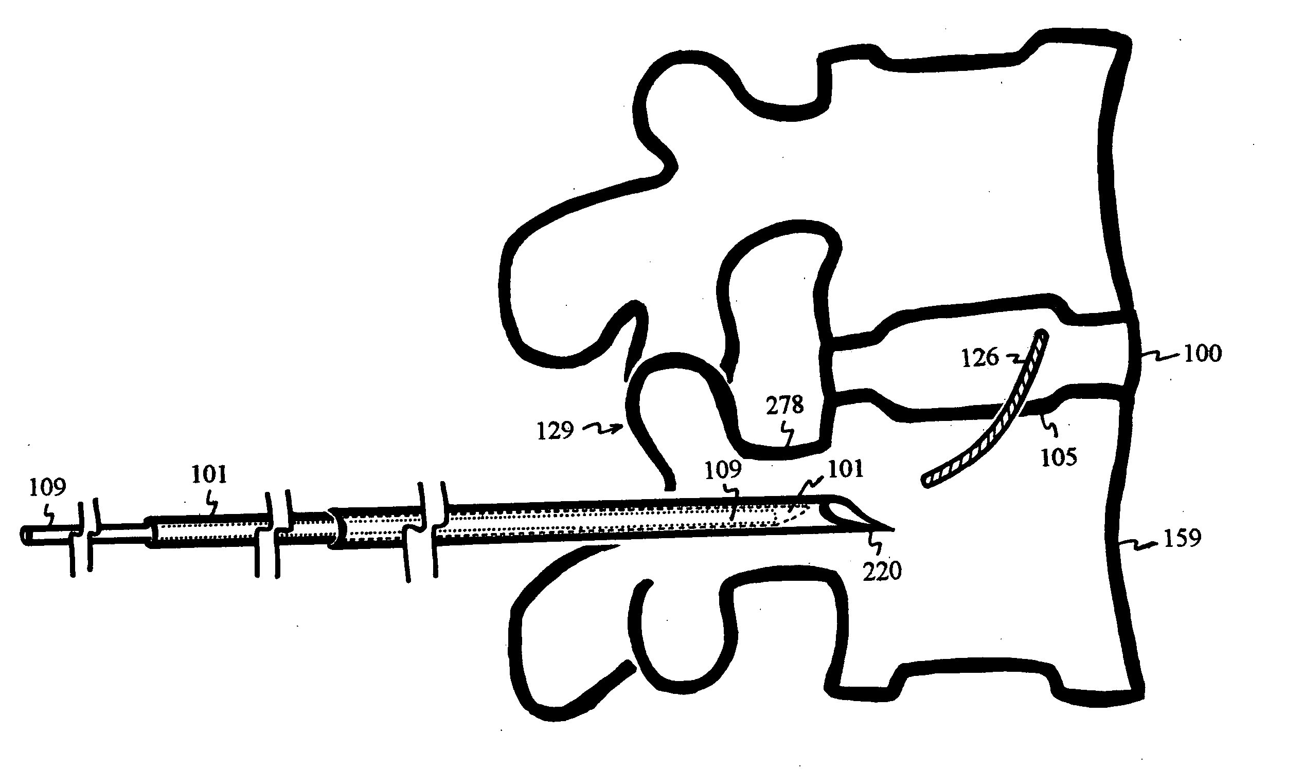
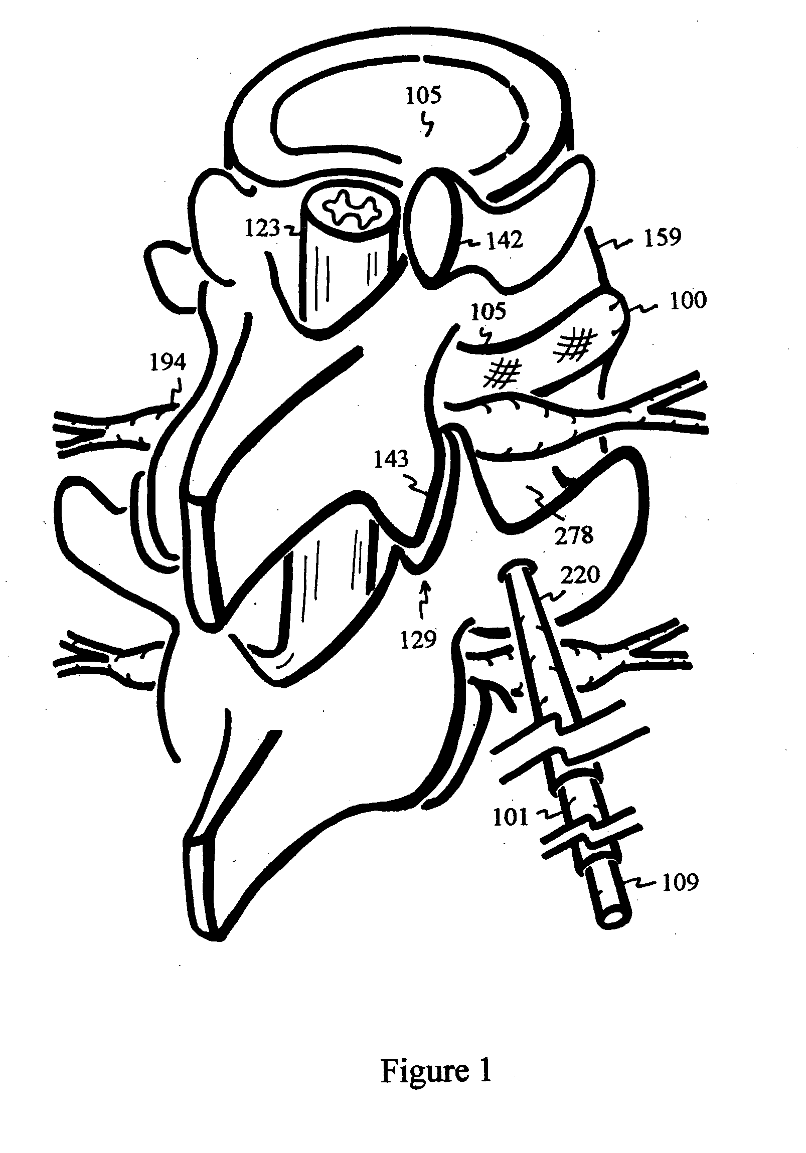
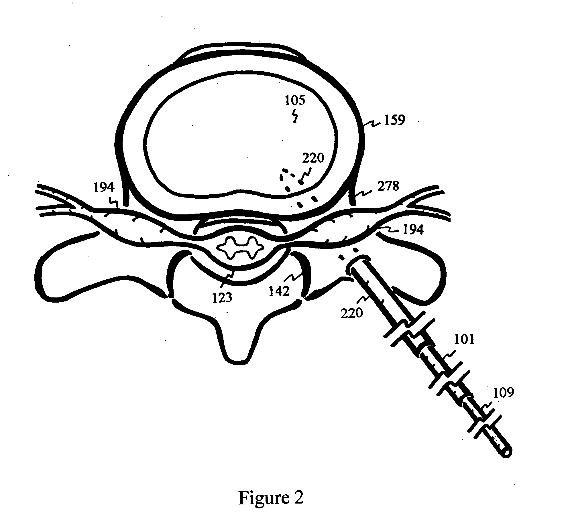
[0142] Pedicle 278 puncturing with a trocar can be guided by a fluoroscope, ultrasound or MRI. The trocar can also be coated with radiopaque, echogenic or magnetic coating to intensify the image. A tubular dilator is inserted over the trocar. The trocar is then replaced with a drill, which drills into the pedicle 278 toward the center of the vertebral body 159.

[0143] The drill is replaced with a conduit 126 delivery device. The delivery device contains a conduit 126 abutted against a plunger 109 within an elastically curved needle 101. The elastically curved needle 101 is resiliently straightened within a rigid needle 220. FIG. 1 shows insertion of the conduit 126 delivery device through the dilator, not shown, into the pedicle 278. The pedicle 278 puncturing circumvents the iliac blockage and prevents potential injury to the nerve 194, as shown in FIG. 2. FIG. 3 shows a side view of a pedicle 278 puncture into the vertebral body 159 with the rigid needle 220 containing the elastic...


PUM


Abstract

The intervertebral disc is avascular. With aging, nutrients and oxygen transporting through the endplates diminish. The disc degenerates, and pain ensues. Conduits are delivered through a pedicle or vertebral body into the intervertebral disc to re-establish the exchange of nutrients and waste between the disc and bodily circulation to slow, stop or reverse disc degeneration and relieve pain. Endplate plugs may be deployed to seal gaps between the conduits and the endplates to prevent immune responses to the nucleus pulposus and to preserve the hydrostatic pressure within the disc.

Description

CROSS-REFERENCES TO OTHER APPLICATIONS [0001] This application is a continuation-in-part of U.S. patent application Ser. No. 10 / 840,816 filed on May 7, 2004. This application also claims priority of U.S. Provisional Applications 60 / 582,228 filed on Jun. 22, 2004; 60 / 587,837 filed on Jul. 14, 2004; and 60 / 660,120 filed on Mar. 8, 2005. [0002] This application is also a continuation-in-part of U.S. patent application Ser. No. 10 / 470,181, filed on Jul. 21, 2003, which is a National Stage Application of PCT / US02 / 04301 filed Feb. 13, 2002, which claimed priority of U.S. Provisional Applications 60 / 268,666 filed on Feb. 13, 2001; 60 / 297,556 filed on Jun. 11, 2001; 60 / 310,131 filed on Aug. 3, 2001; 60 / 325,111 filed on Sep. 26, 2001; and 60 / 330,260 filed on Oct. 17, 2001. This application also claims priority of U.S. Provisional Applications 60 / 468,770 filed on May 7, 2003; 60 / 480,057 filed on Jun. 20, 2003; 60 / 503,553 filed on Sep. 16, 2003; and 60 / 529,065 filed on Dec. 12, 2003.FIELD OF I...

Claims


Application Information

Patent Timeline
Patent Type & Authority Applications(United States)
IPC IPC(8): A61B17/16A61B17/70A61B19/00A61F2/44
CPCA61B17/1604A61B17/1615A61B17/162A61B2019/303A61B17/1637A61B17/1671A61B17/7061A61B17/1624A61B2090/033
Inventor YEUNG, JEFFREY E.
Owner YEUNG JEFFREY E
Why Eureka
Try Eureka