Method and apparatus for facilitating control of a target computer by a remote computer

a remote computer and target computer technology, applied in the field of computer network maintenance, can solve the problems of inability to direct use of servers by maintenance personnel, large computer network, and inability to maintain and control such networks, and achieve the effects of reducing bandwidth usage, improving usability and perceived performance, and increasing processing speed

Inactive Publication Date: 2005-11-03
CARRIGAN BRIAN J +1
View PDF22 Cites 83 Cited by
  • Summary
  • Abstract
  • Description
  • Claims
  • Application Information

AI Technical Summary

Benefits of technology

[0027] Therefore, what is preferred is a KVM system or method which addresses one or more of these problems. The invention will preferably include a KVM system or method having increased processing speed. Preferably, the system will reduce bandwidth usage and provide good usability and perceived performance for the user of the remote computer.

Problems solved by technology

As computer networks have become more and more extensive, the challenges associated with maintenance and control of such networks have become exponentially larger.
Often, computer networks are very large, and may include hundreds or even thousands of servers located in separate server rooms far removed from the location of maintenance personnel.
Therefore, direct use of the servers by maintenance personnel is impractical.
Furthermore, even if the maintenance personnel are on location, it is impractical for them to conduct maintenance activities on hundreds or thousands of target computer servers by moving physically from one server to the next.
However, analog KVM switches have a number of disadvantages.
However, even analog KVM extenders often place strict constraints on the physical distance between the user the target computers.
Another disadvantage of analog KVM switches is that they are not easily scalable.
In other words, creating networks of KVM switches, and adding additional target and remote computers to that network is difficult, usually resulting in escalating costs and reduced performance.
Another related problem with analog KVM switches is that if the remote site is far removed from the target site, the receiver of the KVM switch must be hand-tuned for optimal video performance.
Without such hand tuning, the video quality at the remote computer suffers, resulting in an lower-than-optimal perceived performance.
The requirement of hand-tuning makes the installation of a network of analog of KVM switches cumbersome and expensive.
However, digital KVM also introduces a number of disadvantages not present with analog KVM technology.
The first main disadvantage is perceived performance.
As described above, the rate of data being generated by the target computer's video signal is very large.
Thus, the digital KVM requires a CPU with a very high data processing rate, which translates into higher CPU costs.
In addition, there is less processing power available for other features.
In some applications, security concerns require that the digital KVM be able to encrypt its video, keyboard and mouse information, so that the data cannot be easily intercepted.
However, such encryption requires significantly more CPU processing power.
Historically, this extra power requirement has been a barrier to traditional digital KVM technology providing encryption, except at much higher system costs, or by sacrificing perceived performance.
There are other issues raised by the specific method by which digital KVM technology operates.
There are a number of problems that can arise from improper predictions of pixel timing, resulting in incorrect sampling.
A further effect of incorrect pixel sampling is sample jitter.
This results in the generation of extraneous data, and unnecessary bandwidth usage.
This in turn results in slower response times of the KVM, since there is less bandwidth available to transmit the real differences between the current frame and the previous frame.

Method used


Image

  • Method and apparatus for facilitating control of a target computer by a remote computer
  • Method and apparatus for facilitating control of a target computer by a remote computer
  • Method and apparatus for facilitating control of a target computer by a remote computer

Examples


Embodiment Construction

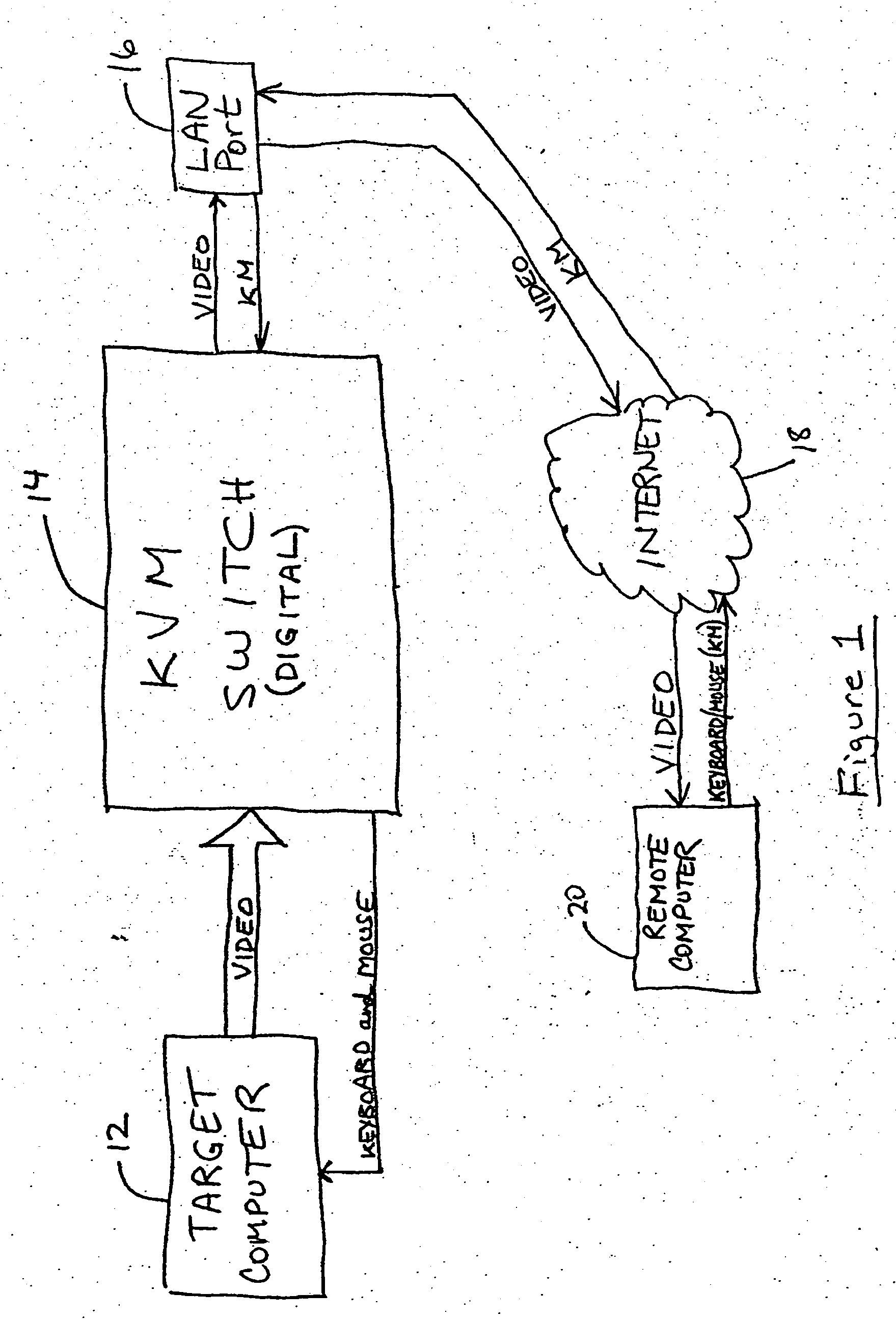
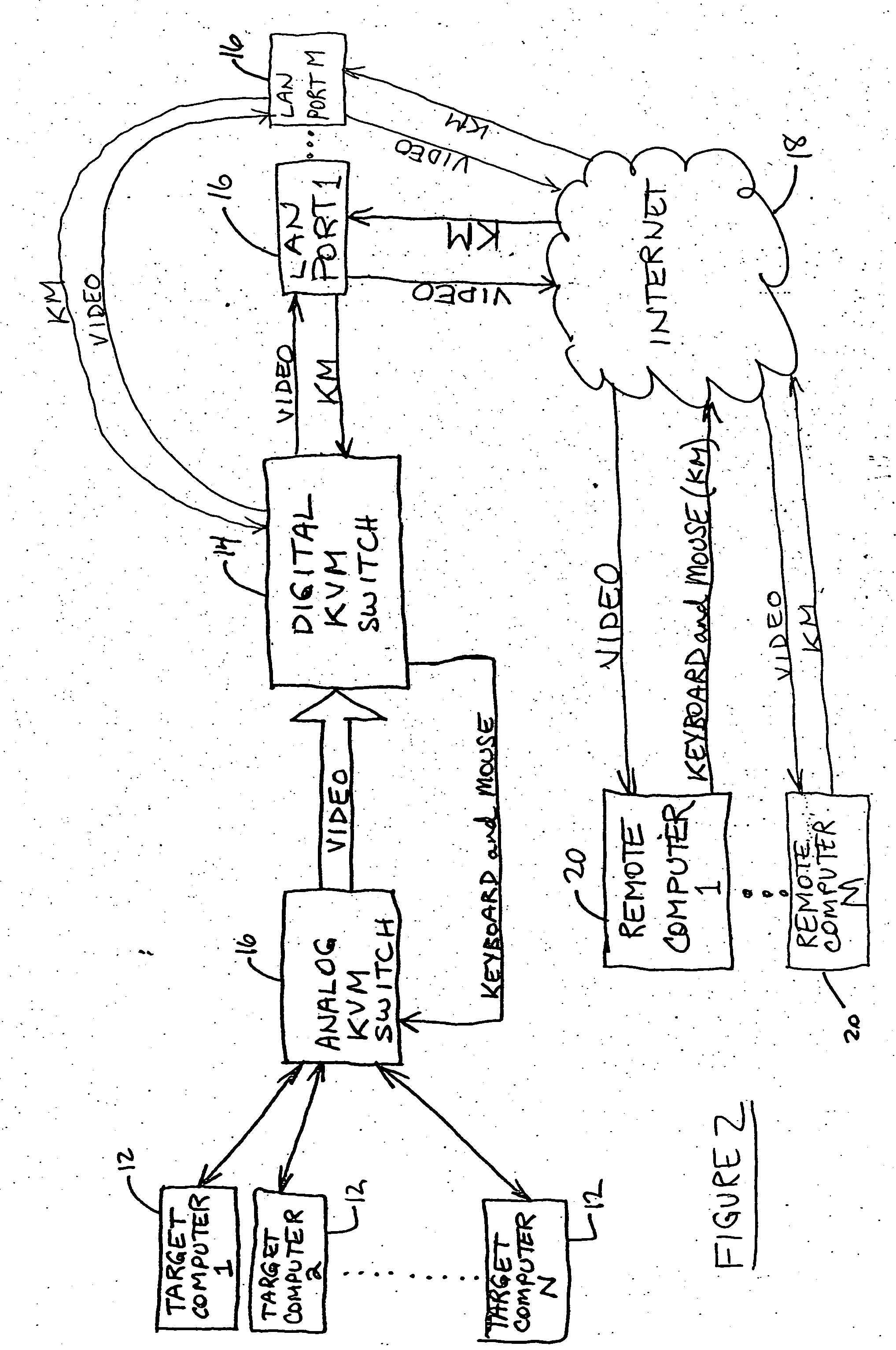
[0076] Referring now to FIG. 1, a target computer 12 is shown. In the embodiment shown in FIG. 1, KVM switch 14 is connected directly to target computer 12, and receives the video signals of target computer 12. In the embodiment shown in FIG. 2, N target computers 12 (N>1) are connected through an analog KVM switch 16 to the digital KVM switch 14. In this way, users of one of M (M>1) remote computers 20, as will be more particularly described below, can receive the video signals of any one of N target computers 12, and control those target computers 12 by the keyboard and mouse signals being transmitted thereto. The user of a remote computer 20 can choose which target computer 12 is controlled by switching the analog KVM switch 16.

[0077] The KVM switch 14 is connected, preferably via a LAN port 16, to the internet, designated by reference numeral 18. The remote computer 20 receives information from the KVM switch 14 via the internet 18. It will be appreciated that the connection be...


PUM


Abstract

A method of capturing video from a target computer to update a remote computer's video with the video output of the target computer. The new video frame comprises a series of new frame pixels to be captured The method comprises (A) receiving for comparison a new frame pixel from the series; then (B) comparing the new frame pixel to a corresponding reference frame pixel; then (C) if the final new frame pixel has not been captured, repeating steps A and B for the next new frame pixel in the series.

Description

FIELD OF THE INVENTION [0001] This invention relates to the field of computer maintenance, and in particular, the field of computer network maintenance. BACKGROUND OF THE INVENTION [0002] As computer networks have become more and more extensive, the challenges associated with maintenance and control of such networks have become exponentially larger. In a typical setting, the operators of computer stations are not the same people as those who maintain the computer hardware and software. In the case of computer server hardware, there are no explicit operators, in the sense that computer servers are not used directly by users to do their work. Instead, users typically do their work at one of many computers connected to the server. Thus, in the case of computer servers, the servers are only used directly when maintenance is being performed on the server. As computer networks have become larger, it has become necessary to have specialized groups of people responsible for maintenance of c...

Claims


Application Information

Patent Timeline
Patent Type & Authority Applications(United States)
IPC IPC(8): G06F3/00G06F3/038G06F3/14G06F11/30G06F15/16G09G3/20G09G5/00
CPCG06F3/023G06F3/038G09G2370/24G09G5/008G09G2310/04G06F3/1462
Inventor CARRIGAN, BRIAN J.GRAY, PETER D.
Owner CARRIGAN BRIAN J
Why Eureka
Try Eureka