Pressure detecting apparatus

a detection apparatus and pressure sensor technology, applied in the field of pressure sensors, can solve the problems of reducing the inability to measure knocking signals, and the weight of the rod is increased, so as to reduce the stress of removing the pressure sensitive element from the printed circuit board, reduce the stress applied to the bump, and reduce the effect of stress

Active Publication Date: 2005-11-17
DENSO CORP
View PDF8 Cites 21 Cited by
  • Summary
  • Abstract
  • Description
  • Claims
  • Application Information

AI Technical Summary

Benefits of technology

[0020] Preferably, the first end of the flexible printed circuit board is disposed in the pipe on one side of an inner wall of the pipe. The second end of the flexible printed circuit board is disposed in the pipe on the other side of the inner wall of the pipe. The one end of the inner wall of the pipe faces the other side of the inner wall of the pipe. In this case, it can be performed appropriately that the bending angle is set to be equal to or smaller than 90 degrees. Further, the stress of removing the pressure sensitive element from the printed circuit board is reduced. Thus, the connection between the element and the board can be appropriately secured.
[0021] Further, pressure detecting apparatus includes: a housing; a flexible printed circuit board disposed in the housing; a sensing portion for detecting pressure and outputting a signal c...

Problems solved by technology

However, as explained above, if the length of the rod is made longer, then the weight of this rod is increased.
Accordingly, such a problem may occur with respect to a sensor characteristic.
That is, knocking signals are embedded in noise which is produced by the resonant phenomenon of the rod, so that the knocking signals cannot be measured.
Further, in the case of such a pressure detecting apparatus that a pressure sensitive element has been connected to a flexible printed-circuit board by way of a flip flop joint, if a cooling/heating cycle is repeatedly carried out, then a large amount of stresses may be produced in the bump joint portions, because of differences in thermal expansion coefficients of these structural elements, in particular, a difference between a thermal expansion coefficient as to the pressure sensitive element made of silicon, and another thermal expansion ...

Method used


Image

  • Pressure detecting apparatus
  • Pressure detecting apparatus
  • Pressure detecting apparatus

Examples


first embodiment

[0051] (First Embodiment)

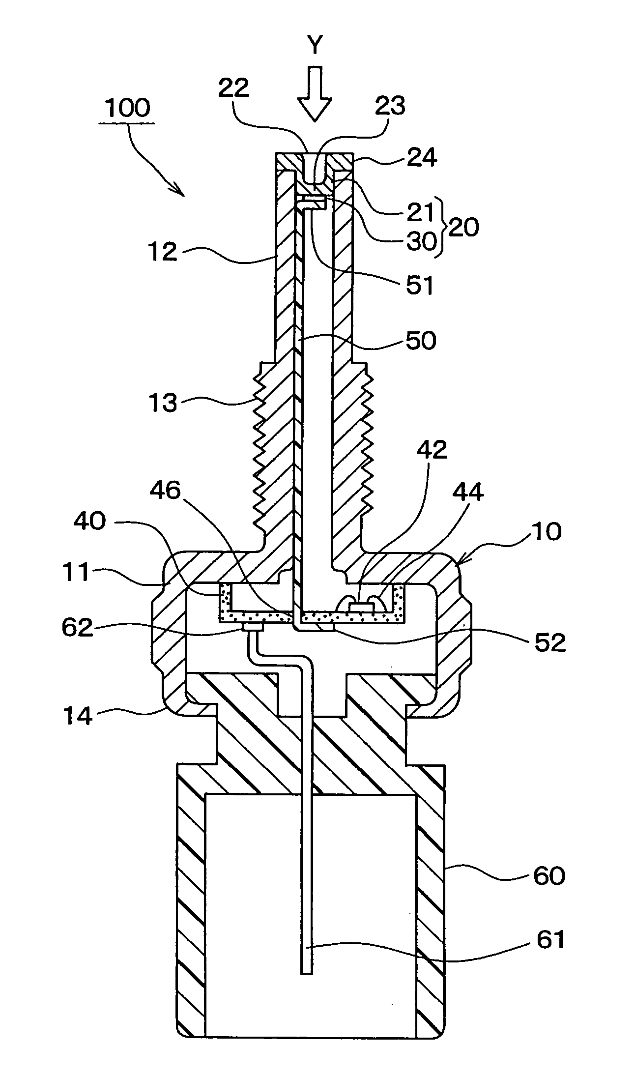
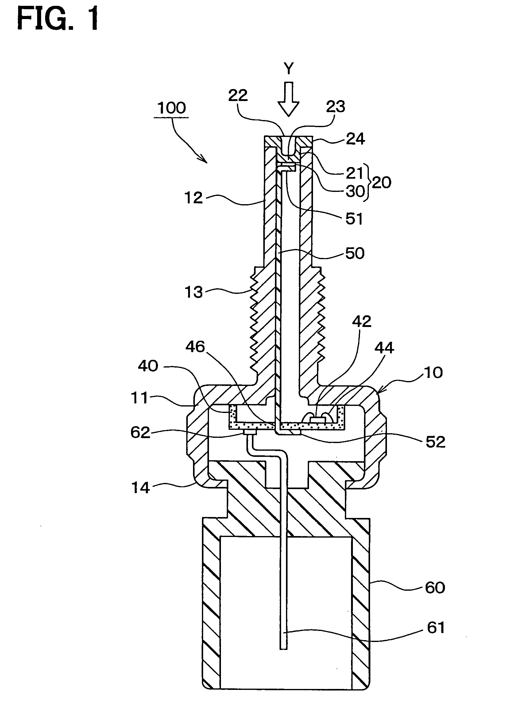
[0052]FIG. 1 is a sectional view for schematically showing an entire structure of a pressure detecting apparatus 100 according to a first embodiment of the present invention. Also, FIG. 2 is an enlarged view for representing a portion of FIG. 1, which is a top end of the apparatus 100. It should be noted that in FIG. 2, an engine block 200 is also represented.

[0053] Although usage of the pressure detecting apparatus 100 is not limited, this pressure detecting apparatus 100 may be applied as a combustion pressure sensor, while a pipe portion 12 of a housing 10 is mounted in a mounting hole 201 formed in, for example, an engine block 200 of an automobile as an object to be detected by way of a screw coupling manner (see FIG. 2). This combustion pressure sensor detects pressure (namely, internal cylinder pressure) within a combustion chamber 202 as a detecting pressure.

[0054] The housing 10 is constituted by a cylindrical main body portion 11 and the pipe por...

second embodiment

[0099] (Second Embodiment)

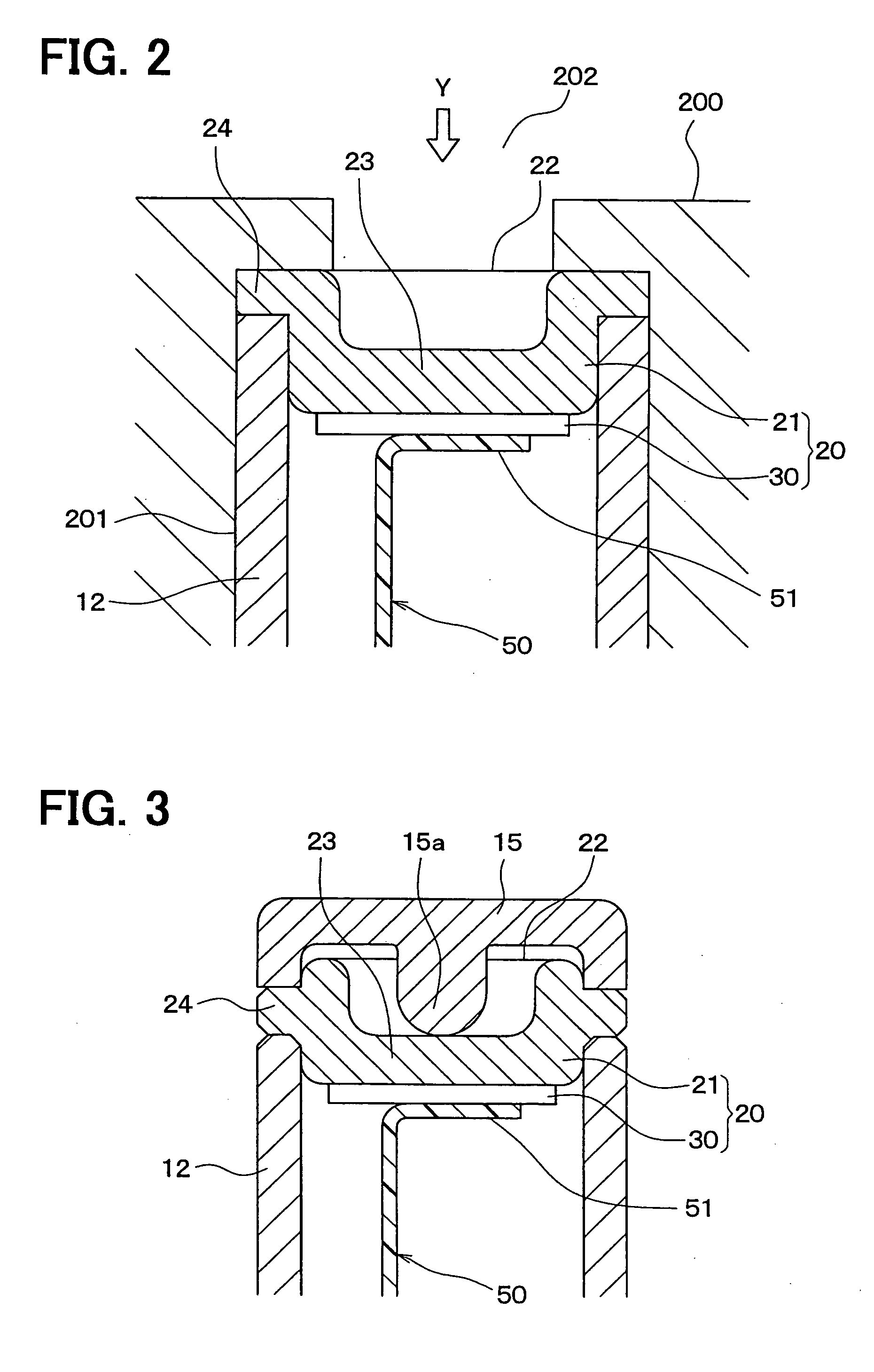
[0100]FIG. 3 is a sectional view for schematically indicating a major portion of a pressure detecting apparatus according to a second embodiment of the present invention. A different point of this pressure detecting apparatus from that of the first embodiment will now be mainly described.

[0101] In the above-described first embodiment, while the pressure sensitive element 20 has been arranged in such a manner that this pressure sensitive element 20 is exposed under the environment of the detecting pressure, the detecting pressure has been directly applied to the pressure sensitive element 20.

[0102] In contrast to the first embodiment, in the pressure detecting apparatus of this second embodiment, as indicated in FIG. 3, a diaphragm 15 has been provided on the tip portion of the pipe portion 12 in the housing 10 in such a manner that this diaphragm 15 covers the pressure sensitive element 20. Thus, detecting pressure may be applied via this diaphragm 15 to ...

third embodiment

[0111] (Third Embodiment)

[0112]FIG. 5 is a sectional view for schematically indicating a major portion of a pressure detecting apparatus according to a third embodiment of the present invention. A different point of this pressure detecting apparatus from that of the above-described embodiment will now be explained.

[0113] As shown in FIG. 5, also in this third embodiment, similar to the above-described second embodiment, the pressure-receiving-purpose diaphragm 15 is provided on the tip portion of the pipe portion 12 in such a manner that this diaphragm 15 covers the pressure sensitive element 20, so that detecting pressure is applied via the pressure-receiving-purpose diaphragm 15 to the pressure sensitive element 20.

[0114] In accordance with the pressure detecting apparatus of the above-described second embodiment, while the convex portion 15a has been provided on the pressure-receiving-purpose diaphragm 15, this pressure-receiving-purpose diaphragm 15 has been directly made cont...


PUM


Abstract

Pressure detecting apparatus includes: a housing; a pipe extending from one end of the housing and having an elongated shape; and a pressure sensitive element for detecting pressure and outputting a signal corresponding to the pressure. The pipe includes a top end capable of receiving the pressure. The pressure sensitive element is disposed on the top end of the pipe. The housing includes a connector for retrieving the signal from the pressure sensitive element. The pipe further includes a wiring member disposed inside the pipe so that the wiring member connects between the pressure sensitive element and connector electrically.

Description

CROSS REFERENCE TO RELATED APPLICATIONS [0001] This application is based on Japanese Patent Applications No. 2004-146095 filed on May 17, 2004, No. 2004-146096 filed on May 17, 2004, and No. 2004-332054 filed on Nov. 16, 2004, the disclosures of which are incorporated herein by reference. FIELD OF THE INVENTION [0002] The present invention relates to a pressure sensor. BACKGROUND OF THE INVENTION [0003] The present invention is related to pressure detecting apparatus, i.e., a pressure sensor arranged in such a manner that a pressure sensitive element is provided inside a housing containing an elongate-shaped pipe portion which is projected from one edge side of the housing. [0004] This sort of pressure detecting apparatus is arranged by employing a housing, an elongate-shaped pipe portion, and a pressure sensitive element, the apparatus which is disclosed, for instance, in Japanese Laid-open Patent Application No. H05-34231. The elongate-shaped pipe portion is provided in such a man...

Claims


Application Information

Patent Timeline
IPC IPC(8): G01L7/08G01L9/00G01L19/14G01L23/18
CPCG01L9/006G01L19/0084G01L23/18G01L19/148G01L19/147G01L9/04
Inventor ODA, TERUO
Owner DENSO CORP
Why Eureka
Try Eureka