Fins on trolling plate mount

a technology of trolling plate and mount, which is applied in the direction of marine propulsion, special-purpose vessels, vessel construction, etc., can solve the problems of slowing the acceleration rate, affecting the forward vision of the operator, and the high attitude of the bow, so as to reduce the bow up attitude of the boat, improve the performance of the recreational watercraft, and contribute to the performance of the watercraft

Inactive Publication Date: 2005-11-17
DYER WILLIAM B
View PDF9 Cites 5 Cited by
  • Summary
  • Abstract
  • Description
  • Claims
  • Application Information

AI Technical Summary

Benefits of technology

[0008] The present invention is embodied within the provision of fin structure for attachment to the lower unit of an outboard motor or an outdrive to improve the performance of a recreational watercraft.
[0009] The fin structure is embodied in fins which project laterally of the outboard lower unit or outdrive and carried by a trolling plate component. The fins are located so as to be in alignment with the trolling plate proper when it is in a retracted position. Positioning of the fins in substantially coplanar fashion with a raised trolling plate contributes to watercraft performance by reducing the bow up attitude of the boat, particularly during acceleration to a speed suitable for water skiing or other recreational uses.
[0010] Important objectives of the present fin invention include providing fin structure that compliments the effect of a raised trolling plate by reducing the tendency of a boat hull to pitch; by contributing to streamlining of a water flowing past an anti-cavitation plate and a raised trolling plate; by reducing the time from start to planing of a boat hull; by providing fin structure which lends itself to selective use, i.e., readily attachable or removable from a mount in place on a propulsion unit; by utilizing a mount already in place on a propulsion unit for another accessory to preclude further modification of anti-cavitation plate.

Problems solved by technology

During acceleration of a boat of the type and size used in towing water skiers or like recreational purposes, it is common for the craft to assume a bow high attitude when starting which hinders the operator's forward vision.
A bow high attitude is also undesirable in that it slows the rate of acceleration.
Trolling plates serve to reduce propeller efficiency or other propulsion unit to lower boat speed which, in view of engine size, could not otherwise be achieved.

Method used


Image

  • Fins on trolling plate mount
  • Fins on trolling plate mount

Examples


Embodiment Construction

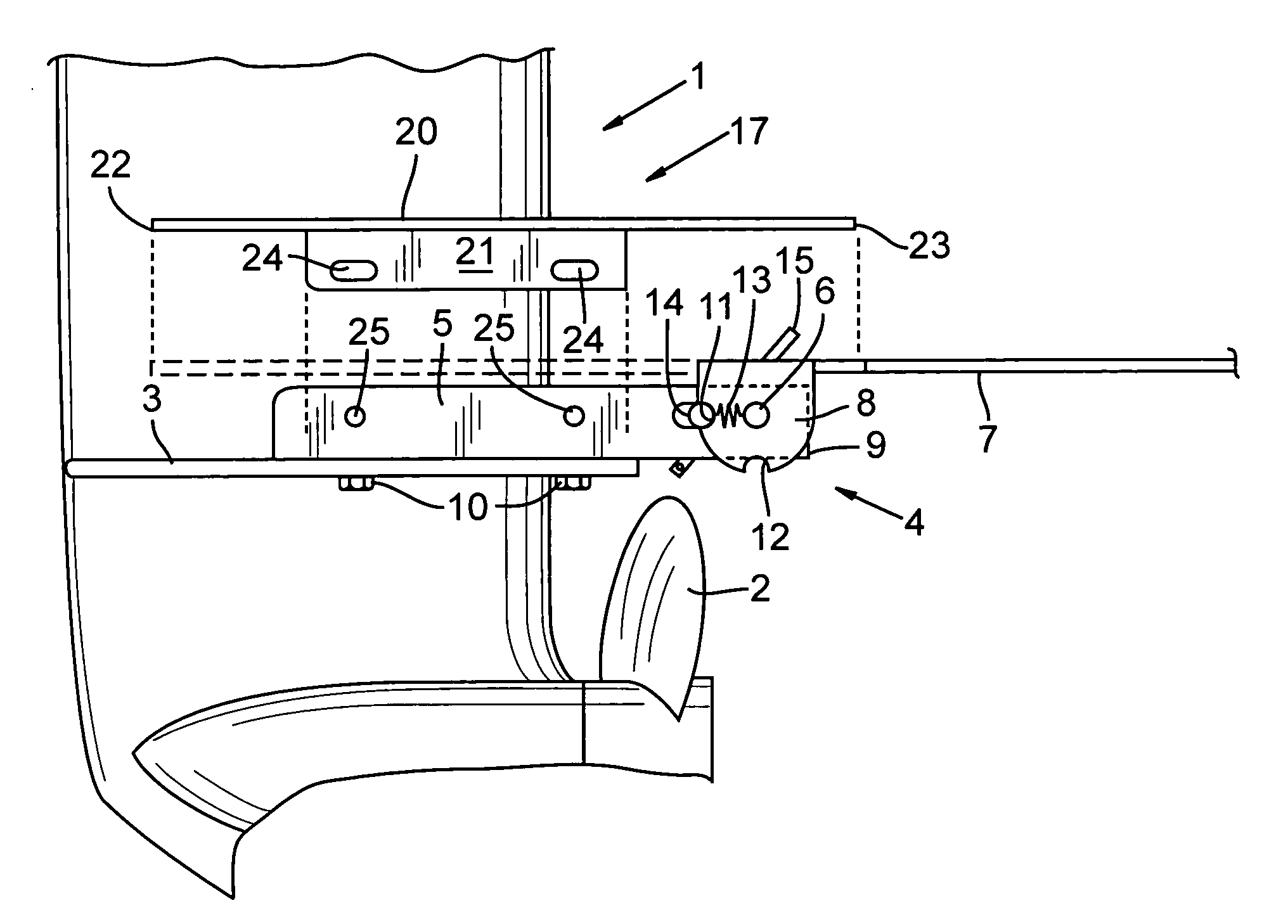
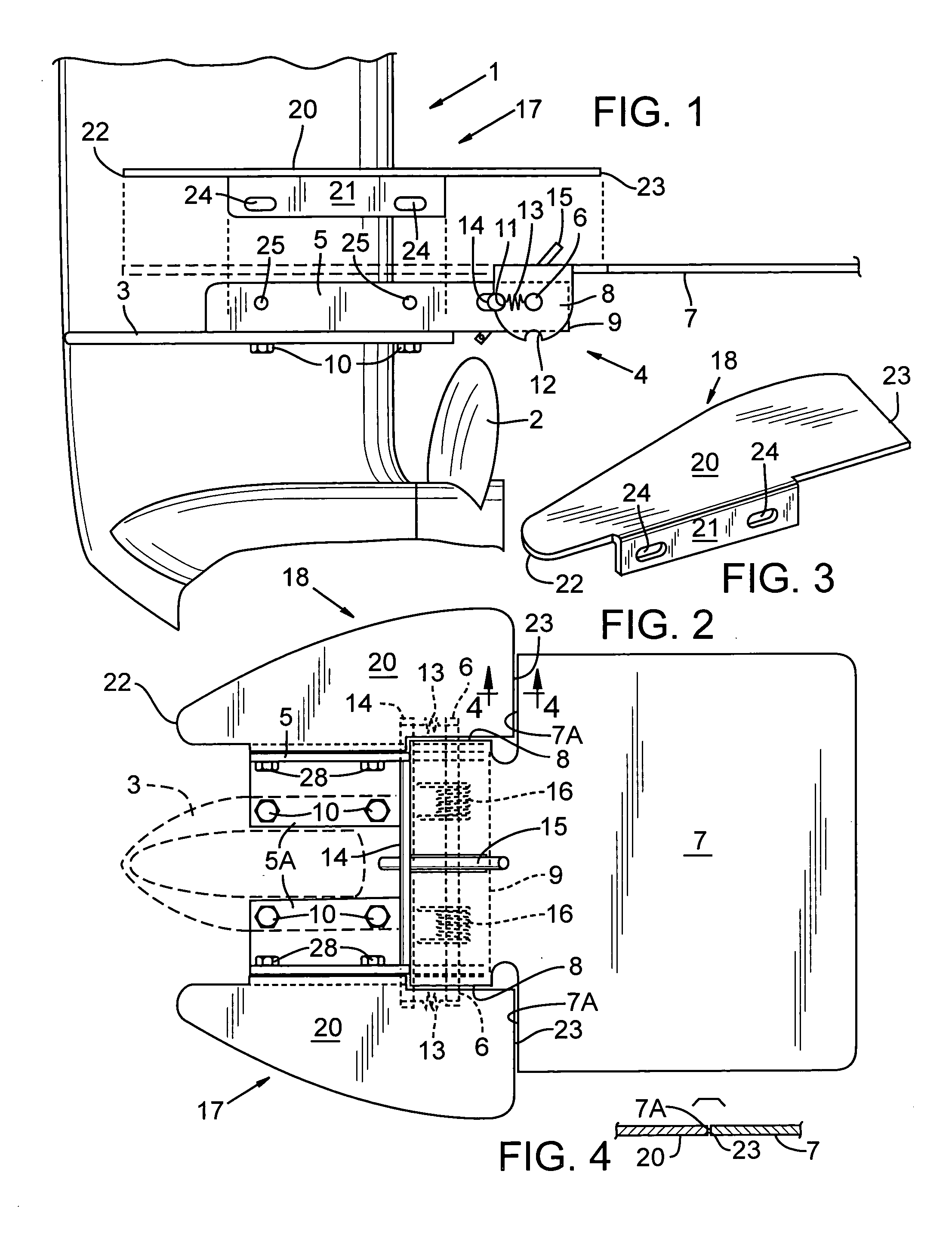
[0016] With further attention to the accompanying drawings wherein applied reference numerals indicate parts similarly hereinafter identified, the reference numeral 1 indicates generally outdrive or lower unit of an outboard motor having a propeller 2. It will be understood that the present invention is not limited to propeller propulsion units, but rather may be utilized in other types of propulsion units found on small watercraft. Typical of outdrives and outboard lower units is an anti-cavitation plate 3. A trolling plate assembly or unit generally at 4 is in typical fashion mounted to an anti-cavitation plate 3 at 3 by a U-shaped bracket 5 and fasteners 10. Bracket 5 terminates rearwardly at 9. Arms 5A of the U-shaped bracket are located astride the outdrive or lower unit 1 of a propulsion unit and are of right angle section and receive an axle 6. Axle 6 serves to pivotally join a trolling plate at 7 to the mounting bracket with the forward end segment of plate 7 having a pair o...


PUM


Abstract

Horizontally disposed fins are located in a plane in alignment with a raised trolling plate with fin trailing edges proximate the leading edge of the raised trolling plate. A mounting bracket of a trolling plate assembly serves to mount the fins superjacent the anti-cavitation plate of a propulsion unit.

Description

BACKGROUND OF THE INVENTION [0001] The present invention is directed toward fins on a watercraft propulsion unit to enhance operation of the watercraft during acceleration and at speed. [0002] During acceleration of a boat of the type and size used in towing water skiers or like recreational purposes, it is common for the craft to assume a bow high attitude when starting which hinders the operator's forward vision. A bow high attitude is also undesirable in that it slows the rate of acceleration. [0003] In recreational boating it is common to utilize a boat for both the towing of skiers, inner tube riders, etc., and for fishing. Such boats are frequently equipped with a trolling plate unit on an outdrive or the lower unit of an outboard motor. Trolling plates serve to reduce propeller efficiency or other propulsion unit to lower boat speed which, in view of engine size, could not otherwise be achieved. For high speeds, such as for water skiing, the trolling plate is retracted to a r...

Claims


Application Information

Patent Timeline
Patent Type & Authority Applications(United States)
IPC IPC(8): B63H20/34B63H25/44
CPCB63H20/34
Inventor DYER, WILLIAM B.
Owner DYER WILLIAM B
Why Eureka
Try Eureka