
Use of electroactive monolayers in generating negative differential resistance behaviors and devices employing the same

a technology of electroactive monolayers and negative differential resistance, which is applied in the direction of solid-state devices, nanoinformatics, instruments, etc., can solve the problem that there is no known sound mechanistic basis for how ndr is generated in molecular systems, and achieve the effect of negative differential resistance and negative differential resistan

Inactive Publication Date: 2005-11-17
NORTH CAROLINA STATE UNIV
View PDF6 Cites 22 Cited by
  • Summary
  • Abstract
  • Description
  • Claims
  • Application Information

AI Technical Summary

Benefits of technology

[0045] In accordance with the present invention, a negative differential resistance (NDR) device is provided, along with a method of making the NDR device, and method of generating NDR using the NDR device. In one embodiment, the NDR device comprises: a substrate comprising a conductor material or a semi-conductor material; and a self-assembled monolayer (SAM) disposed on the substrate, wherein the SAM comprises a first electroactive moiety and a spacer moiety, the spacer moiety defining a barrier between the electroactive moiety and the substrate, wherein the NDR device exhibits negative differential resistance in the presence of a varying applied voltage.

Problems solved by technology

Indeed, there is currently no known sound mechanistic basis as to how NDR is generated in molecular systems.

Method used


Image

  • Use of electroactive monolayers in generating negative differential resistance behaviors and devices employing the same
  • Use of electroactive monolayers in generating negative differential resistance behaviors and devices employing the same
  • Use of electroactive monolayers in generating negative differential resistance behaviors and devices employing the same

Examples


example 1

Laboratory Example 1

SAMs Containing Redox-Active Head Groups Display Molecular NDR

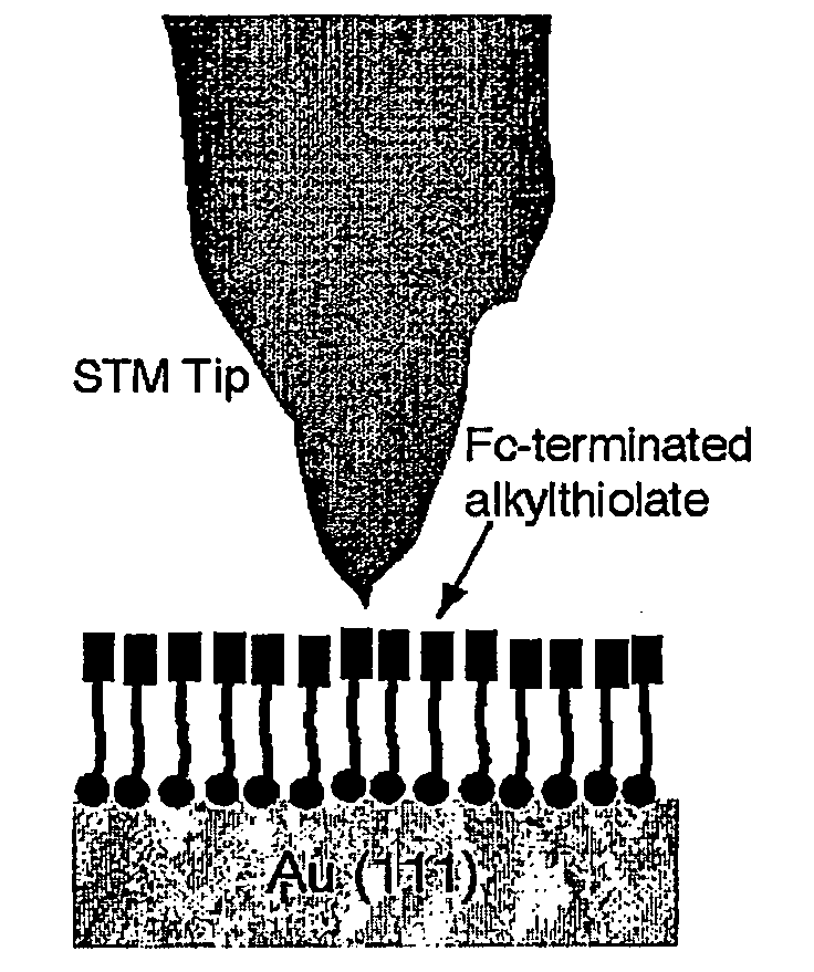
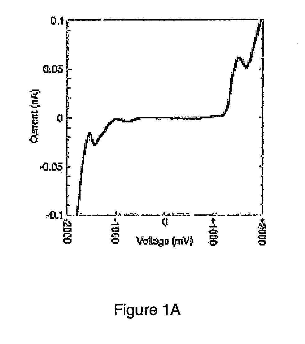
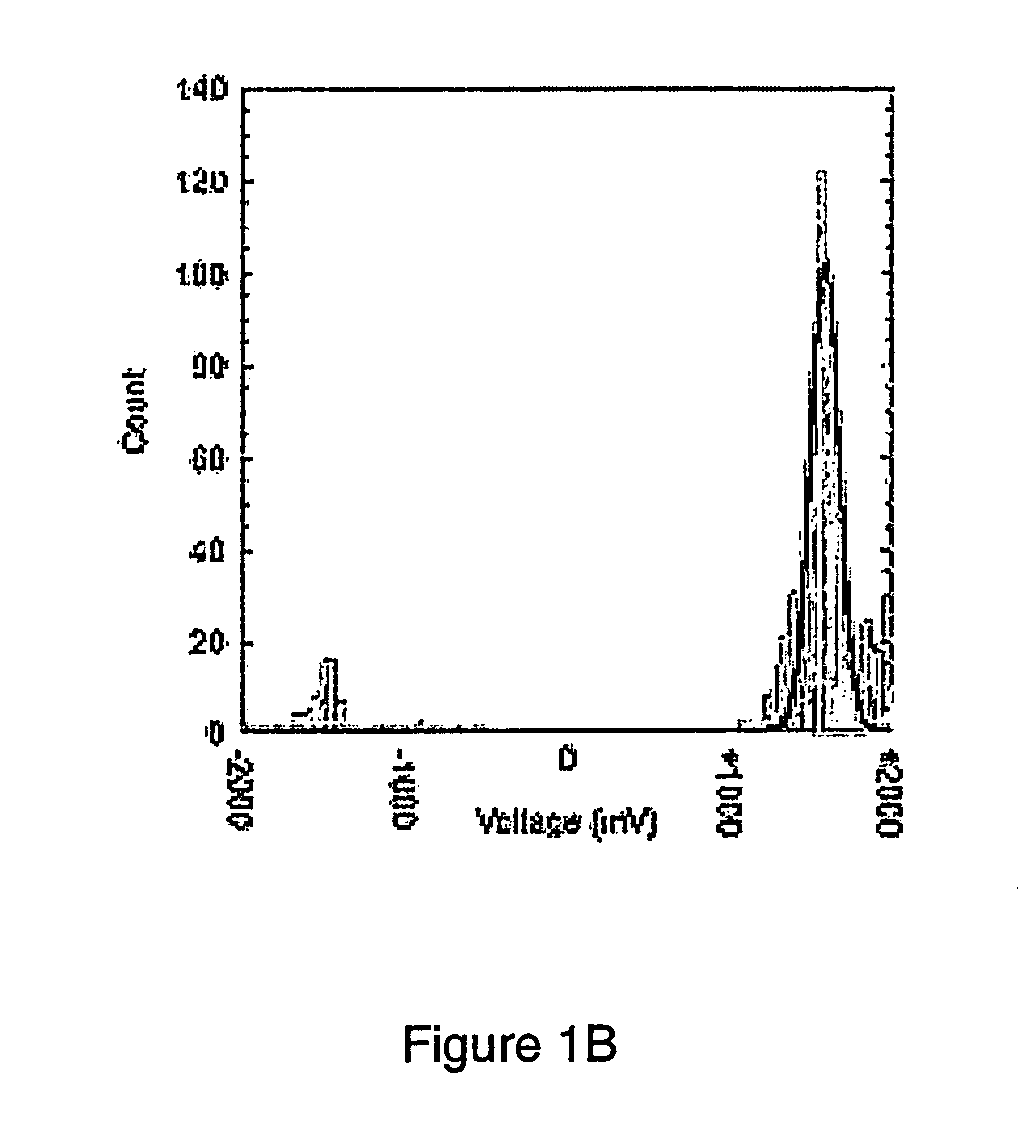
[0190] It was hypothesized that SAMs containing redox-active head groups could display molecular NDR. To test this, a ferrocenyl-undecanethiolate (Fc-C11S—) SAM (Uosaki et al., (1991) Langmuir7: 1510-1514) was prepared on a Au(111) surface (Table 1 provides the structures of the molecules employed in Laboratory Examples 1-4). Using scanning tunneling microscopy (STM) under conditions of low setpoint current, a set of current-voltage (I-V) curves was obtained using continuous imaging tunneling spectroscopy (CITS). In this procedure, 1024 I-V curves were collected on a region of the surface. Although many investigations of molecular I-V behavior are performed under high vacuum conditions, these data were taken under an inert fluid (dodecane). The reasons for this experimental condition will be made clear when patterning experiments are described below. FIG. 1A shows a typical I-V curve from the CITS dat...

example 2

Laboratory Example 2

Evaluation of Resonant Tunneling

[0197] Prior to the disclosure of the present invention presented herein, little experimental evidence has been available that differentiates resonant tunneling as the mechanism of NDR from that of adventitious oxidation / reduction of the electroactive species in the junction. In an attempt to rule out an electrochemical mechanism, I-V curves were collected at different voltage sweep rates varying well over a decade (six values from 2.3 to 60.0 V / s). In all cases, the magnitude and position of the NDR response were similar to those data shown in FIGS. 1A and 1B. If an electrochemical mechanism were operative (e.g., that found in thin layer voltammetry), one would expect to see an influence on the I-V behavior as this parameter was varied. This was not observed.

[0198] Assuming a resonant tunneling mechanism, the I-V response of a nonelectroactive SAM (in the present Laboratory Example, a dodecanethiolate SAM, C12S-SAM, i.e. a SAM p...

example 3

Laboratory Example 3

Other Electroactive SAMs

[0203] It was hypothesized that other electroactive SAMs would display an I-V response similar to that of the Fc-C11S-SAM. To this end, scanning tunneling lithography was employed to place Fc-C11S-SAM and a phenoxygalvinol-substituted hexanethiol (Gal-C6S-SAM) (Shultz & Tew, (1994) J. Org. Chem.59: 6159-6160; Sagara et al., (1998) Langmuir 14: 3682-3690) adjacent to one another in a background of C12S-SAM. FIGS. 5A-5C shows the results of one series of patterning of both the Fc-C11S-SAM (as the letters “Fc”) and the Gal-C6S-SAM (as the letters “Gal”) into a C12S-SAM. The increased tunneling current through the electroactive SAM at biases near the position of NDR was observed as an increase in apparent height difference between an electroactive and a nonelectroactive SAM. At low bias (115 mV, FIG. 5A), the apparent height difference between the three SAM regions was extremely small, and the patterns of the electroactive SAMs were almost in...


PUM

PropertyMeasurementUnit
scan sizeaaaaaaaaaa
bias voltageaaaaaaaaaa
sizeaaaaaaaaaa

Abstract

A negative differential resistance (NDR) device, along with a method of making the NDR device, and a method of generating NDR using the NDR device. The NDR device includes: a substrate comprising a conductor material or a semi-conductor material; and a self-assembled monolayer (SAM) disposed on the substrate, wherein the SAM includes a first electroactive moiety and a spacer moiety, the spacer moiety defining a barrier between the electroactive moiety and the substrate, wherein the NDR device exhibits negative differential resistance in the presence of a varying applied voltage. Other aspects of the invention include: (1) NDR in multilayers in which the peak to valley ratio of the NDR response can be controlled by the number of layers; (2) modulation of NDR using binding groups to one of the electrical contacts; (3) modulation of NDR using binding groups to the electroactive moiety itself; and (4) NDR devices that display multiple peaks in the current-voltage curve that contain electroactive moieties that have multiple low potential electrochemical oxidations and / or reductions.

Description

CROSS REFERENCE TO RELATED APPLICATIONS [0001] This application is based on and claims priority to U.S. Provisional Application Ser. No. 60 / 359,946, filed Feb. 27, 2002, herein incorporated by reference in its entirety.GRAND STATEMENT [0002] This work was supported by a grant from the Office of Naval Research, Grant No. N00014-00-1-0633. Thus, the U.S. government has certain rights in the invention.TECHNICAL FIELD [0003] The present invention relates to negative differential resistance-based structures and applications. Abbreviations [0004] AFM atomic force microscope or microscopy [0005] Au gold [0006] C6SH hexanethiol [0007] C6S-SAM A SAM formed from hexanethiol [0008] C7SH heptanethiol [0009] C11SH undecanethiol [0010] C12SH dodecanethio [0011] C16SH hexadecanethiol [0012] CCD charge coupled display [0013] CD cyclodextrin [0014] CITS continuous imaging tunneling spectroscopy [0015] Fc ferrocene [0016] Fc-C11SH ferrocenylundecanethiol [0017] Gal-C6SH phenoxygalvinol-substituted he...

Claims


Application Information

Patent Timeline
Patent Type & Authority Applications(United States)
IPC IPC(8): G11C13/02H01L29/10H10K99/00
CPCB82Y10/00B82Y30/00G11C11/39G11C13/0014H01L51/0595G11C2211/5614G11C2213/81H01L51/0077G11C13/025Y10S977/703Y10S977/705Y10S977/72Y10S977/702Y10S977/755H10K85/30H10K10/701
Inventor GORMAN, CHRISTOPHER B.CARROLL, RICHARD LLOYDCREDO, GRACE
Owner NORTH CAROLINA STATE UNIV
Learn More