Lighting apparatus

a technology of light-emitting apparatus and light-emitting layer, which is applied in the direction of lighting and heating apparatus, discharge tube luminescnet screen, instruments, etc., can solve the problems of reducing yield, difficult to uniformly form an el layer in a large area, and extremely thin el elements

Inactive Publication Date: 2005-11-17
TOYOTA IND CORP
View PDF5 Cites 25 Cited by
  • Summary
  • Abstract
  • Description
  • Claims
  • Application Information

AI Technical Summary

Benefits of technology

[0009] Accordingly, it is an objective of the present invention to provide a lighting apparatus having a plurality of luminescent panels emitting isotropic light, which apparatus eliminates necessity

Problems solved by technology

However, EL elements are extremely thin, having an EL layer of thickness of several tens to several hundreds nanometers.
It is thus difficult to uniformly form an EL layer in a large area.
Such attempt would result in a reduced yield.
The totally reflected light cannot be effectively used.
However, when applied to a panel in a lighting apparatus used as a backlight for a liquid crystal display, the method has the following drawbacks.
This reduces yields.
The objectives of the publications are

Method used


Image

  • Lighting apparatus
  • Lighting apparatus
  • Lighting apparatus

Examples


first embodiment

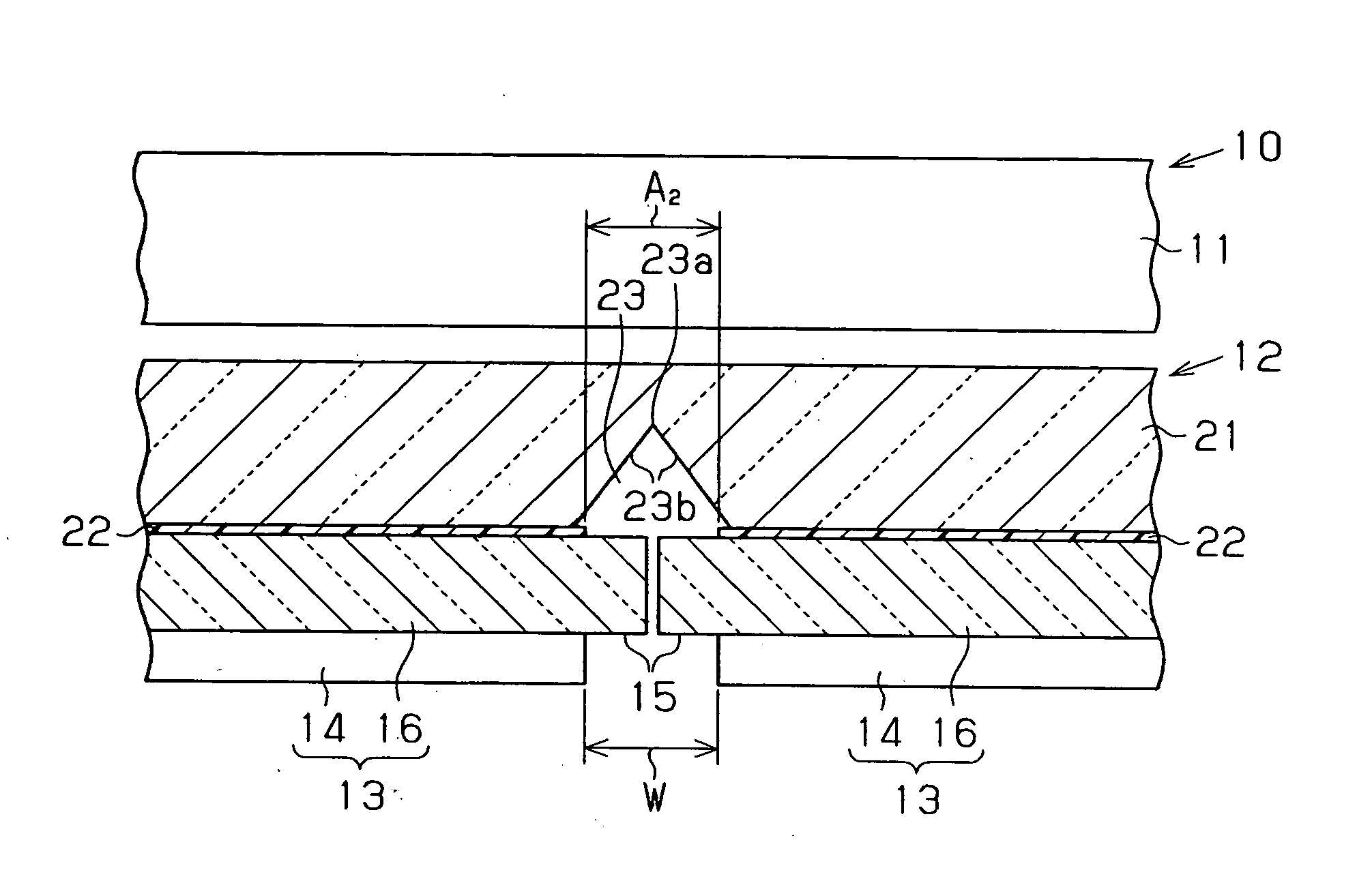
[0036] A lighting apparatus 12 according to the present invention will now be described referring to FIGS. 1(a) to 4(b). The lighting apparatus 12 is used as a backlight of a liquid crystal display 10. In the cross-sectional views, part of hatching is omitted.

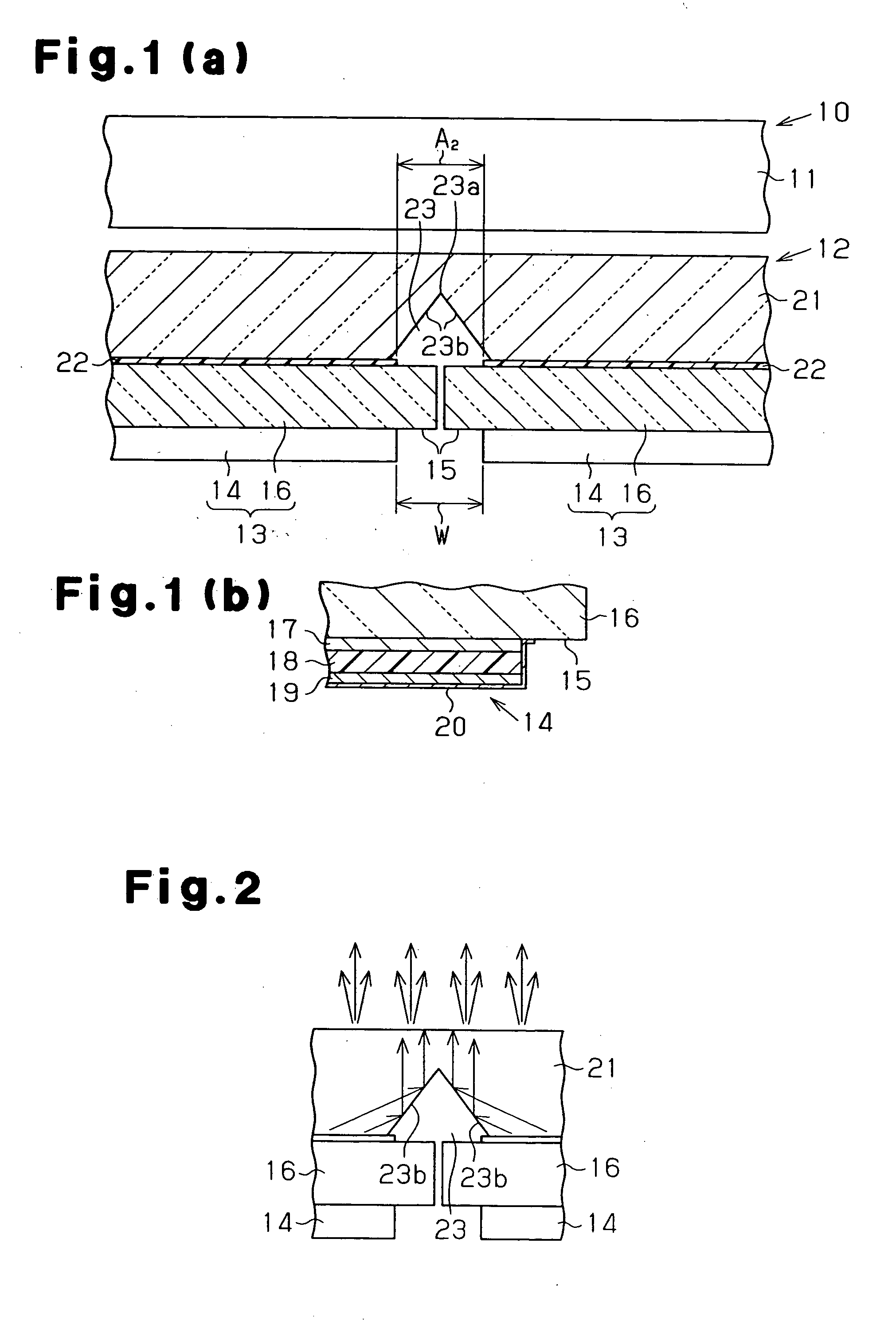
[0037] As shown in FIG. 1(a), the liquid crystal display 10 includes a transmissive liquid crystal panel 11 and the lighting apparatus 12 located on the back of the liquid crystal panel 11, or on a surface at a side opposite to a display surface. The lighting apparatus 12 has luminescent panels 13. Each luminescent panel 13 includes a light emitting portion 14, which emits isotropic light, and a non-light emitting portion 15 provided around the light emitting portion 14. The luminescent panels 13 are arranged so that the non-light emitting portions 15 are arranged adjacent to each other. The number of the luminescent panels 13 is determined according the size of each luminescent panel 13 and the size of the lighting apparatus 1...

second embodiment

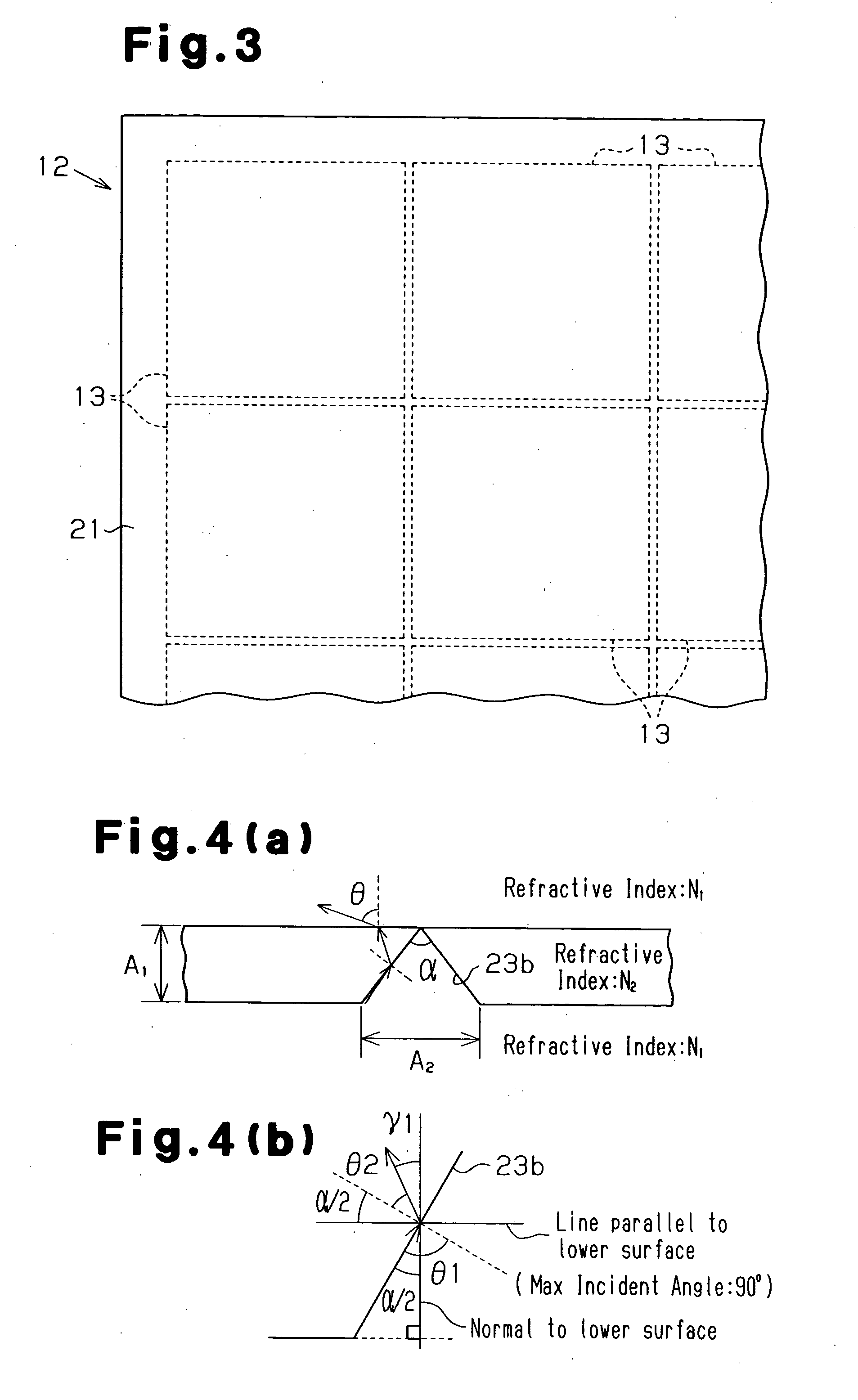
[0069] However, in the second embodiment, the diffusion portions 24 are provided on sections of a surface of the brightness compensating member 21 that faces the luminescent panels 13 except for the V-shaped grooves 23. A space exists between each diffusion portion 24 and the corresponding luminescent panel 13. Thus, light that exits each luminescent panel 13 is incident on the brightness compensating member 21 through a layer of air. Since the refractive index of air is 1.0 and the refractive index of the transparent substrates 16 is 1.5, the angle of refraction at the layer of air is greater than the incident angle of light from the luminescent panel 13 to the layer of air due Snell's law. Thus, light that is incident on the layer of air from the luminescent panel 13 at a large incident angle is hardly incident on the brightness compensating member 21, while light emitted frontward from each luminescent panel 13, that is, light emitted in a direction along the thickness of the bri...

third embodiment

[0078] In the third embodiment, since the second V-shaped grooves 26 are formed on a surface of the brightness compensating member 21 that is opposite to the surface on which the V-shaped grooves 23 are formed, the depth A1 of the V-shaped grooves 23 can be reduced for the same viewing angle. The thickness of the brightness compensating member 21 is reduced, accordingly. For the same thickness of the brightness compensating member 21, the viewing angle can be increased.

[0079] Referring to FIGS. 8(a), 8(b), and 8(c), the procedure for obtaining equations for computing the viewing angle θ and setting the thickness of the brightness compensating member 21 will now be explained. As shown in FIGS. 8(a) and 8(c), the equations for the lower side of the brightness compensating member 21 are the same as those in the first embodiments, and the equations (3), (5), and (6) are satisfied. However, in the equation (6), γ1 represents the angle defined by light that is incident on an inclined surf...


PUM


Abstract

A luminescent panel has a light emitting portion for emitting isotropic light and a non-light emitting portion. A brightness compensating member has an incident portion and a light exit portion. The incident portion includes at least one inclined surface that is inclined relative to the light exit portion. The inclined surface is arranged to correspond to the non-light emitting portion. The inclined surface is configured so that the brightness of a section of the brightness compensating member that corresponds to the light emitting portion is substantially equal to the brightness of a section of the brightness compensating member that corresponds to the non-light emitting portion. Therefore, a substantially uniform brightness is obtained from the light exit portion.

Description

BACKGROUND OF THE INVENTION [0001] The present invention relates to a lighting apparatus. Specifically, the present invention relates to a lighting apparatus having a plurality of luminescent panels, in which each panel includes a light emitting portion for emitting isotropic light such as an electroluminescent element (EL element), and a non-light emitting portion provided around the light emitting portion (EL element), and the panels are arranged so that the non-light emitting portions are adjacent to each other. [0002] The present invention also relates to a lighting apparatus having a luminescent panel that includes a light emitting portion for emitting isotropic light such as an EL element, and a non-light emitting portion. [0003] Conventionally, lighting apparatuses having EL elements arranged on a transparent substrate have been proposed. There has also been proposed a technique for using such lighting apparatus as a backlight for a liquid crystal display. There is a demand f...

Claims


Application Information

Patent Timeline
IPC IPC(8): G02F1/13357F21S2/00F21Y105/00H01J1/62H01L27/32H01L51/50H01L51/52H05B33/02H05B33/12H05B33/14
CPCH01L27/3293H01L51/5036H01L2251/5361H01L51/5271H01L51/5206H10K59/18H10K50/125H10K50/814H10K50/856H05B33/22
Inventor BESSHI, NORIYUKIISHIKAWA, HARUYUKITAKEUCHI, NORIHITOTOEDA, MINORUYOSHIDA, MIKIOKOIKE, SHUJI
Owner TOYOTA IND CORP
Why Eureka
Try Eureka