
Inlet casing and suction passage structure

a suction passage and inlet casing technology, applied in the direction of machines/engines, stators, liquid fuel engines, etc., can solve the problems of hardly being formed, affecting the affecting the overall shape of the internal passage, so as to achieve the effect of simple spiral shape, easy formation, and high uniformity

Active Publication Date: 2005-11-17
HITACHI IND PROD LTD
View PDF17 Cites 14 Cited by
  • Summary
  • Abstract
  • Description
  • Claims
  • Application Information

AI Technical Summary

Benefits of technology

[0010] The present invention is devised in view of the above-mentioned conventional problems, and accordingly, an object of the present invention is to provide a suction passage structure which can effectively avoid occurrence of a deviation of a cavitations inducing zone and as well can simplify the configuration of the internal passage, and to provide fluid machinery using such a suction passage structure.
[0011] To the end, according to the present invention, there is provided a suction passage structure provided in fluid machinery for boosting the pressure of fluid through rotation of an impeller mounted on a rotary shaft, for sucking the fluid into the fluid machinery, having an inlet casing including an internal passage connected to a suction passage provided being orthogonal to the rotary shaft on the upstream side in the stream of the fluid directed to the fluid machinery, the internal passage being formed in a spiral shape so as to induce a swirl stream in the fluid, orthogonal to the rotary shaft, characterized in that a rectifying element capable of distributing flow rates in the swirl stream between the center side and the outer peripheral side of the swirl stream in the internal passage, and also capable of causing fluid flowing from the suction passage into the internal passage to deflect the swirl stream into a swirling direction within the internal passage is provided in the vicinity of an inlet of the internal passage.
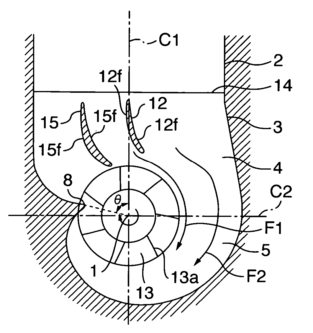
[0018] The guide vane in the present invention, can exhibit a rectifying action for distributing flow rates in the swirl stream in the internal passage on the upstream side of the internal passage, between the swirl center side and the swirl outer peripheral side, and also exhibits a rectifying action for deflecting the fluid into a swirling direction of the swirl stream in the internal passage on the upstream side of the internal passage. Further, with these rectifying action, a rectified swirl stream can be easily formed in the internal passage. As a result, the suction passage and the internal passage in a symmetric configuration can be used for inducing a swirl stream which is effective for preventing occurrence of a deviation of a cavitations inducing zone, that is, a swirl stream which is rectified and which has higher uniformity, and accordingly, the spiral shape of the internal passage can be relative simple, thereby it is possible to facilitate the design and fabrication thereof.
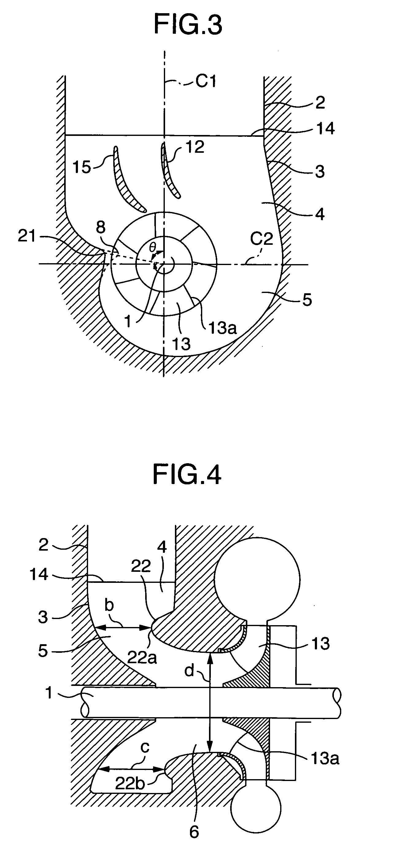
[0019] Further, in the present invention, the projecting height of the bell-mouth part which is provided being projected at the upstream end of the introduction part in the internal passage is gradually decreased from the upstream side to the downstream side, and further, the projecting height of the heighest projecting part of the bell-mouth part on the upstream side and that of the lowest projecting part on the downstream side are formed so as to satisfy a predetermined relationship therebetween. Thus, according to the present invention, it is possible to enhance the uniformity of the stream at the suction opening of the fluid machinery so as to effectively prevent occurrence of a deviation of the cavitations inducing zone.

Problems solved by technology

As a result, there have been raised such disadvantages that a zone where cavitations are caused would be deviated, and further, serious vibration and noise would be possibly caused.
However, the prewhirl type suction passage structure has raised such a problem that the suction passage and the internal passage can hardly be formed, symmetric to each other with respect to the first reference line C1 as in the nonprewhirl type one.
In such an asymmetric configuration, it is required to provide a connection 106 between the suction passage 102 and the internal passage 112 in relatively upstream side part, resulting in occurrence of such a problem that the inlet casing 111 inevitably has a large size.
As a result, there has been raised such a problem that the design and fabrication thereof becomes complicated, resulting in an increase the costs thereof.
However, it has not been sufficient with these elements to always main required uniformity of the stream, and accordingly, the suction passage and the internal passage are inevitably formed, symmetric to each other as in the example shown in FIG. 7.
The nonprewhirl type suction passage structure may have the suction passage and the internal passage which are symmetric with each other, and accordingly, there may be offered such an advantage the shape of the internal passage can be simple so that it can be easily designed and fabricated but also offered such a disadvantage that a deviation of the cavitations inducing zone likely to occur.
Meanwhile, the prewhirl type suction passage structure may avoid occurrence the problem of a deviation of the cavitations inducing zone, but the configuration of the internal passage becomes complicated so as to raise such a problem that the costs thereof is increased in view of its design and fabrication.

Method used


Image

  • Inlet casing and suction passage structure
  • Inlet casing and suction passage structure
  • Inlet casing and suction passage structure

Examples


Embodiment Construction

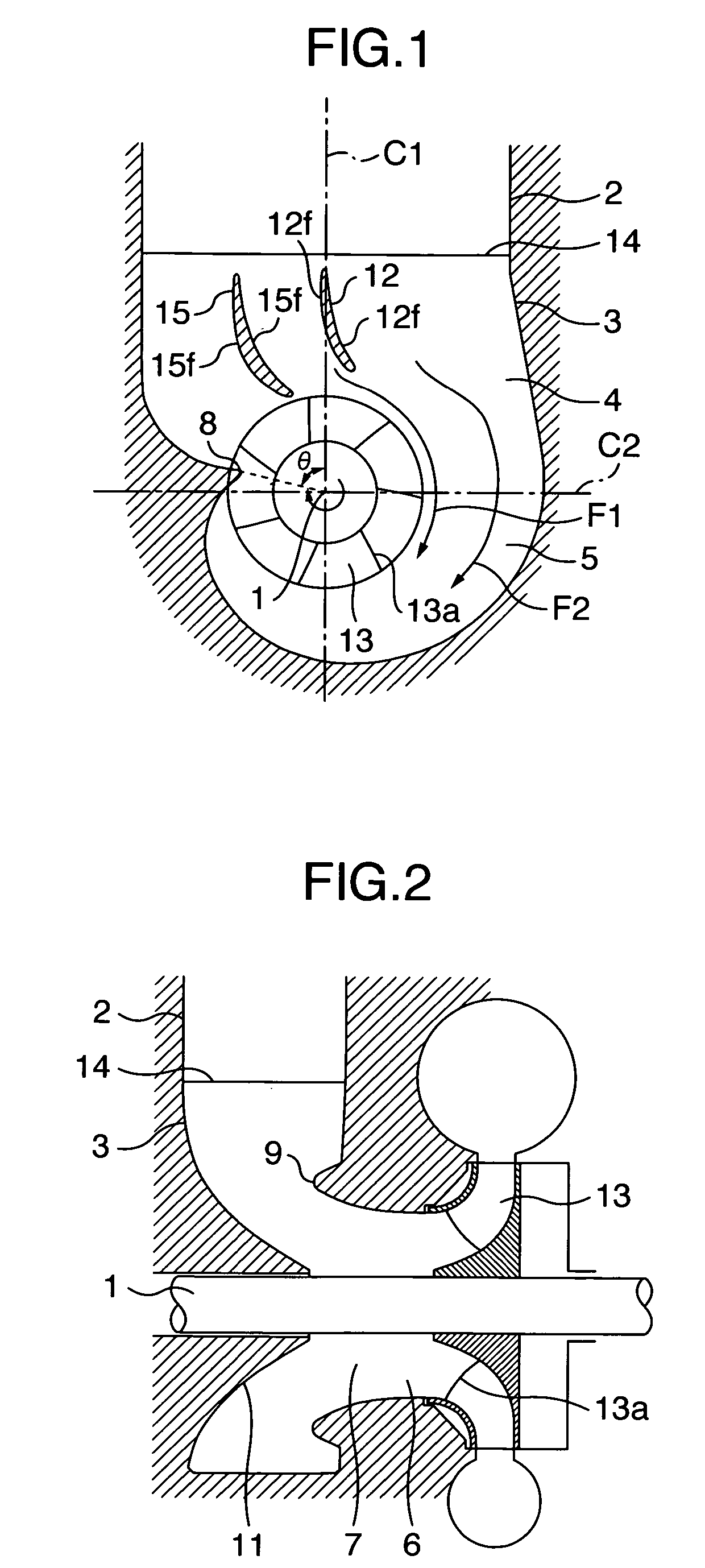
[0029] Explanation will be hereinbelow made of preferred embodiment of the present invention. A configuration of a suction passage structure in a first embodiment is schematically shown in FIGS. 1 and 2. FIG. 1 is a view illustrating the suction passage structure, being sectioned in a plan direction, and FIG. 2 is a view, being sectioned along a reference line C1 in FIG. 1. The suction passage structure in this embodiment is composed of a suction passage 2 arranged being orthogonal to a rotary shaft 1 of rotary machinery, on the upstream side in the direction of a stream of the fluid toward the fluid machinery, in combination of an inlet casing 3.

[0030] The suction casing 3 is provided therein with an inernal passage 4 which is composed of a swirling part 5 in such a spiral shape that a swirl stream orthogonal to the rotary shaft is induced in the fluid introduced through the suction passage 2, that is, a swirl stream rotating around the rotary shaft 1 or an extension of the rotary...


PUM


Abstract

A prewhirl type inlet casing for inducing a spiral stream in fluid comprising a suction passage arranged on an upstream side, being orthogonal to a rotary shaft of fluid machinery, and an internal passage connected to the suction passage, the internal passage being formed in a spiral shape so as to induce a swirl stream orthogonal to the rotary shaft in the fluid. A guide vane is provided in the fluid passage in the inlet casing. The guide vane has a rectifying function capable of distributing flow rates in the swirl stream of the fluid in the internal passage between the swirl center side and the swirl outer peripheral side and has a rectifying function capable of causing the fluid to deflect into the swirling direction of the swirl stream induced by the internal passage. With these rectifying functions, a rectified swirl stream can be easily created in the in internal passage so as to prevent occurrence of a deviation of a cavitations inducing zone. With this configuration, it is possible to effectively prevent occurrence of the deviation of the cavitations inducing zone in order to aim at simplifying the configuration of the internal passage.

Description

BACKGROUND OF THE INVENTION [0001] The present invention relates to an inlet casing or a suction passage structure which is used for suction of fluid into fluid machinery for boosting up the pressure of fluid through the rotation of an impeller mounted on a rotary shaft, and also to a fluid machinery including a pump, a compressor, a blower or the like, using thereof. In a large-sized suction passage structure, an inlet casing produced as a coupling component for the fluid machinery and used for sucking fluid into a fluid machinery is in general connected to a suction passage which is a concrete construction or the like. The above-mentioned suction passage structure includes a non prewhirl type one in which fluid is led in a form of a suction stream into an inlet opening of fluid machinery, in parallel with a first reference line passing through the center line of a rotary shaft of the fluid machine and extending along the stream of fluid directed to the fluid machine in the suction...

Claims


Application Information

Patent Timeline
IPC IPC(8): F04D29/44F04D29/66
CPCF04D29/4213F04D29/4273F04D29/448F04D29/542F04D29/548F04D29/444F05D2250/51
Inventor INOUE, YASUHIROAKI, TAKASHIKAWABATA, SEIJITANAKA, SADASHI
Owner HITACHI IND PROD LTD
Learn More