Optical recording medium

a recording medium and optical technology, applied in the field of optical recording mediums, can solve the problems of difficult to read recorded data similarly to the existing optical recording medium, the tilt margin t is extremely small, and the reflected laser beam may not be correctly returned to the photodetector, so as to prevent the cost-up and minimize the effect of warpag

Inactive Publication Date: 2005-11-17
TDK CORPARATION
View PDF5 Cites 5 Cited by
  • Summary
  • Abstract
  • Description
  • Claims
  • Application Information

AI Technical Summary

Benefits of technology

[0033] According to the present invention, it is possible to provide an optical recording medium capable of preventing the cost-up while minimizing the warpage.

Problems solved by technology

However, when a large warpage occurs in the optical recording medium due to a change in temperature while it is used, since the incident angle of the laser beam to the optical recording medium is varied, the reflected laser beam may not be correctly returned to the photodetector.
However, when the numerical aperture NA of the objective lens for focusing the laser beam increases, as can be seen from Expression 1 below, a problem occurs in that a tolerable angle error in the tilt of an optical axis of the laser beam with respect to the optical recording medium, that is, a tilt margin T extremely decreases.
However, when a large warpage occurs in the next-generation type optical recording medium, it also becomes difficult to read recorded data similarly to the existing optical recording medium.
Furthermore, generally, a label surface is formed on the rear side of the optical recording medium so as to indicate the type of the optical recording medium or the information stored in the optical recording medium or carry out a decorative design, which causes a manufacturing process to be complicated, which results in cost-up.
Further, it is possible to suppress the warpage occurring on the optical recording medium by forming the resin layer with a resin film having almost the same property as that of the supporting substrate on the surface of the supporting substrate instead of forming the resin layer on the rear surface of the supporting substrate, but such a resin film is expensive and manufacturing facility needs to be added for the resin film, which is not preferable because it causes more cost-up.

Method used


Image

  • Optical recording medium
  • Optical recording medium
  • Optical recording medium

Examples


examples

[0097] Hereinafter, examples will be described for clarity of effects of the present invention.

first example

[0098] Sample 1 was manufactured in the following way.

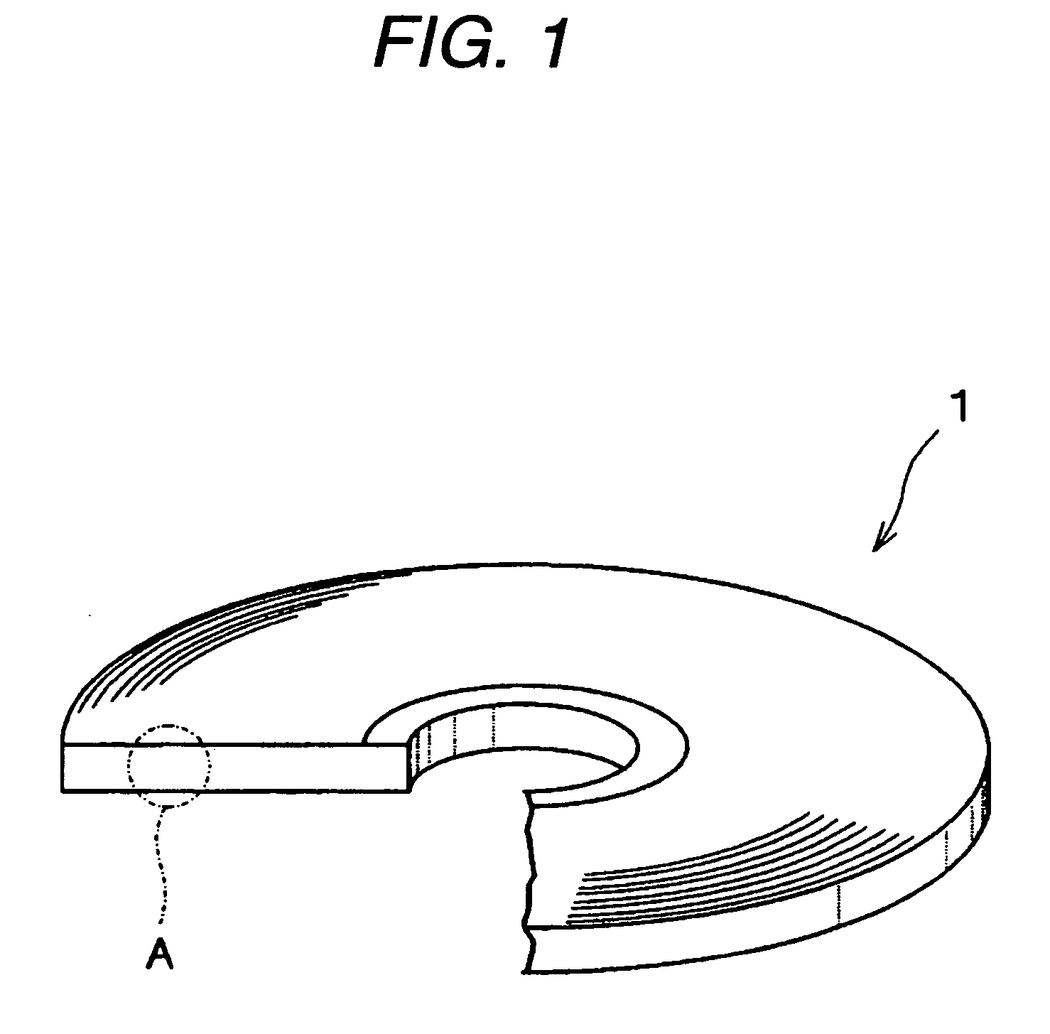
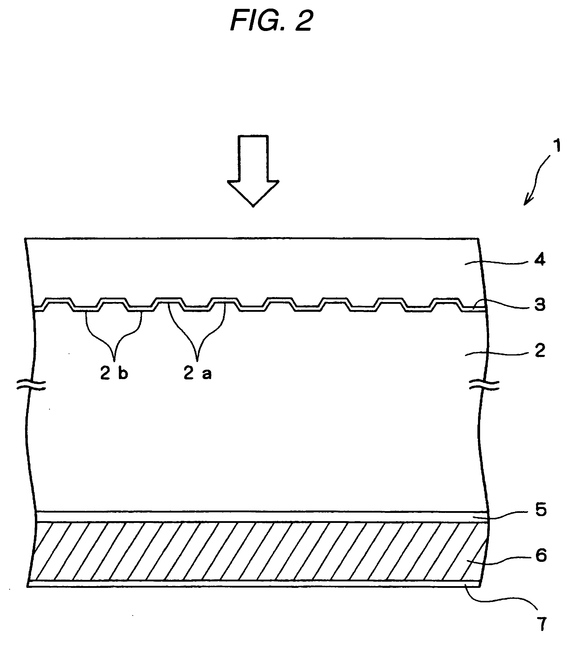
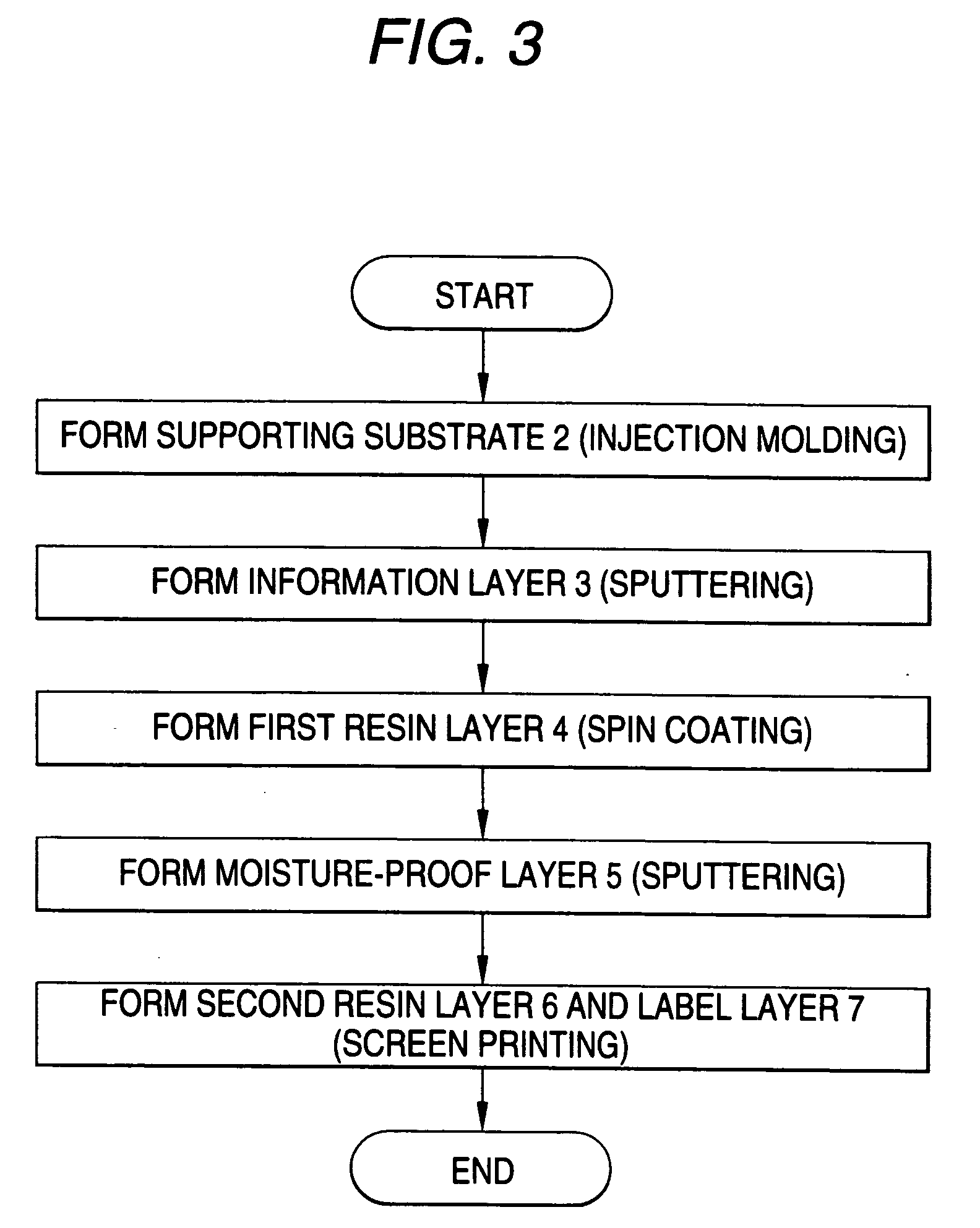
[0099] First, a disk-shaped polycarbonate substrate having a thickness of 1.1 mm and an outer diameter of 120 mm was manufactured by means of injection molding.

[0100] Subsequently, an information layer was formed on a surface of the polycarbonate substrate by a sputtering method.

[0101] Subsequently, a UV curable resin A having the composition below was prepared.

[0102] [UV curable resin A][0103] urethane acrylate (NEGAMI CHEMICAL INDUSTRIAL Co. Ltd.:PRODUCT NAME ‘ART RESIN UN-5200’) . . . 50% by weight [0104] trimethyllolpropantriacrylate (NIPPON KAYAKU KABUSIKIKAISHA: PRODUCT NAME ‘KARAYAD TMPTA’) . . . 33% by weight [0105] phenoxy hydroxy propyl acrylate (NIPPON KAYAKU KABUSHIKIKAISHA: PRODUCT NAME ‘KARAYAD R-128’) . . . 14% by weight 1-hydroxy cyclo hexyl phenyl ketone (NIPPON CHIBAGAIGI [0106] KABUSHIKIKAISHA: PRODUCT NAME ‘IRG184’) . . . 3% by weight

[0107] Furthermore, the viscosity of the UV curable resin A was measured...

example 2

[0126] Sample 8 was manufactured as below.

[0127] First, an information layer was formed on a surface of a polycarbonate substrate having a thickness of 1.1 mm by a sputtering method.

[0128] Subsequently, a UV curable resin B having the composition below was prepared.

[0129] [UV Curable Resin B][0130] urethane acrylate (NEGAMI KABUSHIKIKAISHA: PRODUCT NAME ‘ART RESIN UN-2500’) . . . 45% by weight [0131] tripropylene glycol diacrylate (OSAKA ORGANIC KABUSHIKIKAISA: PRODUCT NAME ‘BISCOAT 310’) . . . 40% by weight iso desyl acrylate (SARTOMER COMPANY, Inc.: PRODUCT NAME ‘SR-395’) . . . 12% by weight [0132] 1-hydroxycyclohexylphenylketone (NIPPON CHIBAGAIGI KABUSHIKIKAISHA: PRODUCT NAME ‘IRG184’) . . . 3% by weight

[0133] Furthermore, the viscosity of the UV curable resin in which alumina was contained was measured using the above-described B type viscometer. The viscosity of the UV curable resin was 3800 mpa·s in an environment of 25° C.

[0134] Subsequently, a polycarbonate substrate i...


PUM

PropertyMeasurementUnit
thicknessaaaaaaaaaa
thixotropic indexaaaaaaaaaa
particle diameteraaaaaaaaaa

Abstract

The optical recording medium includes a supporting substrate 2, an information layer 3 formed on a surface of the supporting substrate 2, a first resin layer 4 formed on the information layer 3 and having a thickness of 30 to 200 μm, a moisture-proof layer 5 formed on a rear surface of the supporting substrate 2, a second resin layer 6 formed on the moisture-proof layer 5 and having a thickness of 30 to 200 μm, and a label layer 7 formed on the second resin layer 6. The second resin layer 6 contains a filler and is formed by a screen printing method.

Description

BACKGROUND OF THE INVENTION [0001] The present invention relates to an optical recording medium and more particularly, to an optical recording medium capable of preventing cost-up and minimizing warpage. [0002] Optical recording media represented by Compact Disk (CD) or Digital Versatile Disk (DVD) have been widely used as a recording medium for recording digital data up to now. These optical recording media may be classified into reproduction-dedicated optical recording media such as CD-ROM or DVD-ROM in which data cannot be recorded or rewritten, recordable optical recording media such as CD-R or DVD-R in which data can be recorded but cannot be rewritten, and rewritable optical recording media such as CD- RW or DVD-RW in which data can be rewritten. [0003] When data are reproduced from these optical recording media, a laser beam set for the reproduction is first irradiated on the optical recording medium. Since recording marks or pits formed in the optical recording medium is dif...

Claims


Application Information

Patent Timeline
Patent Type & Authority Applications(United States)
IPC IPC(8): B32B3/02B41J3/407G11B7/24G11B7/24053G11B7/254G11B7/2542G11B7/257G11B7/26G11B23/00G11B23/40
CPCB41J3/4071G11B7/24053G11B7/24067G11B7/2433G11B7/2472G11B23/40G11B7/252G11B7/2534G11B7/2542G11B23/0021G11B7/248
Inventor YAMADA, TAKASHIKOMAKI, TSUYOSHIUSHIDA, TOMOKI
Owner TDK CORPARATION
Why Eureka
Try Eureka