Cooling device controlling apparatus, cooling device failure detecting apparatus, cooling device failure detecting method, and computer readable recording medium recording program for causing computer to execute detection of failure of cooling device capable of detecting failure in short period efficiently

a technology of cooling device and control apparatus, which is applied in the direction of electric devices, light and heating apparatus, machines/engines, etc., can solve the problems of failure of cooling fan control, deterioration of cell performance and cell life, etc., and achieve the effect of efficiently detecting the failure of the cooling fan in a short period

Inactive Publication Date: 2005-11-24
TOYOTA JIDOSHA KK
View PDF2 Cites 29 Cited by
  • Summary
  • Abstract
  • Description
  • Claims
  • Application Information

AI Technical Summary

Benefits of technology

[0016] Accordingly, an object of the present invention is to provide a cooling device controlling apparatus capable of detecting a failure of a cooling fan in a short period efficiently.
[0017] Another object of the present invention is to provide a cooling device failure detecting apparatus and a cooling device failure detecting method capable of detecting a failure of a cooling fan in a short period efficiently.
[0018] Still another object of the present invention is to provide a computer readable recording medium recording a program for causing a computer to execute detection of a failure of a cooling device capable of detecting a failure of a cooling fan in a short period efficiently.
[0048] According to the present invention, the failure detection of a cooling fan is performed only at a timing when an auxiliary battery is initialized, such as at shipment from a factory or at a repair service, and not performed until the next initialization of the auxiliary battery. Therefore, the frequency of performing failure detection is minimized, and the failure detection can be performed efficiently.
[0049] Further, by setting the timing of the failure detection of a cooling fan at a timing when the auxiliary battery is replaced with a new one, the full performance of the auxiliary battery to be a precondition is ensured, whereby the accuracy of detecting a failure of the cooling fan is improved and the performance of the cooling fan can be maintained at a constant level.
[0050] Still further, as the failure detection of a cooling fan is performed at a prescribed time of an early stage after actuation of a vehicle system, the failure detection can be performed in a short period as compared to conventional failure detecting methods performing the failure detection by detecting the battery temperature.

Problems solved by technology

The increase in the cell temperature causes deterioration of cell performance and cell life.
There may be a failure of the cooling fan such as disconnection or melting of a connection.
There may be a failure of control of the cooling fan.
With such a failure, the cooling ability of the cooling fan is inhibited, and the main battery is hardly kept in an appropriate condition.
On the other hand, according to the methods for detecting a failure of a cooling fan described above, since a change in the battery temperature is employed as an index for a failure detection determination, a failure of the cooling fan cannot be detected unless the vehicle system is actuated to drive the motor and the battery is caused to operate normally.
Therefore, it has been difficult to perform failure detection efficiently at shipment from a factory or at a repair service.
Further, with the conventional methods for detecting a failure of a cooling fan, sometimes detection is performed with unduly frequency, since a detection operation is performed every time the vehicle system is actuated.

Method used


Image

  • Cooling device controlling apparatus, cooling device failure detecting apparatus, cooling device failure detecting method, and computer readable recording medium recording program for causing computer to execute detection of failure of cooling device capable of detecting failure in short period efficiently
  • Cooling device controlling apparatus, cooling device failure detecting apparatus, cooling device failure detecting method, and computer readable recording medium recording program for causing computer to execute detection of failure of cooling device capable of detecting failure in short period efficiently
  • Cooling device controlling apparatus, cooling device failure detecting apparatus, cooling device failure detecting method, and computer readable recording medium recording program for causing computer to execute detection of failure of cooling device capable of detecting failure in short period efficiently

Examples


Embodiment Construction

[0057] In the following, an embodiment of the present invention is described in detail referring to the drawings. Throughout the drawings, an identical reference character is allotted to identical or corresponding components.

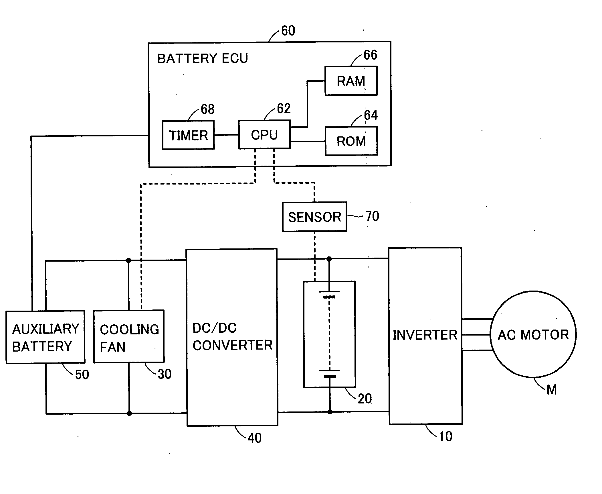
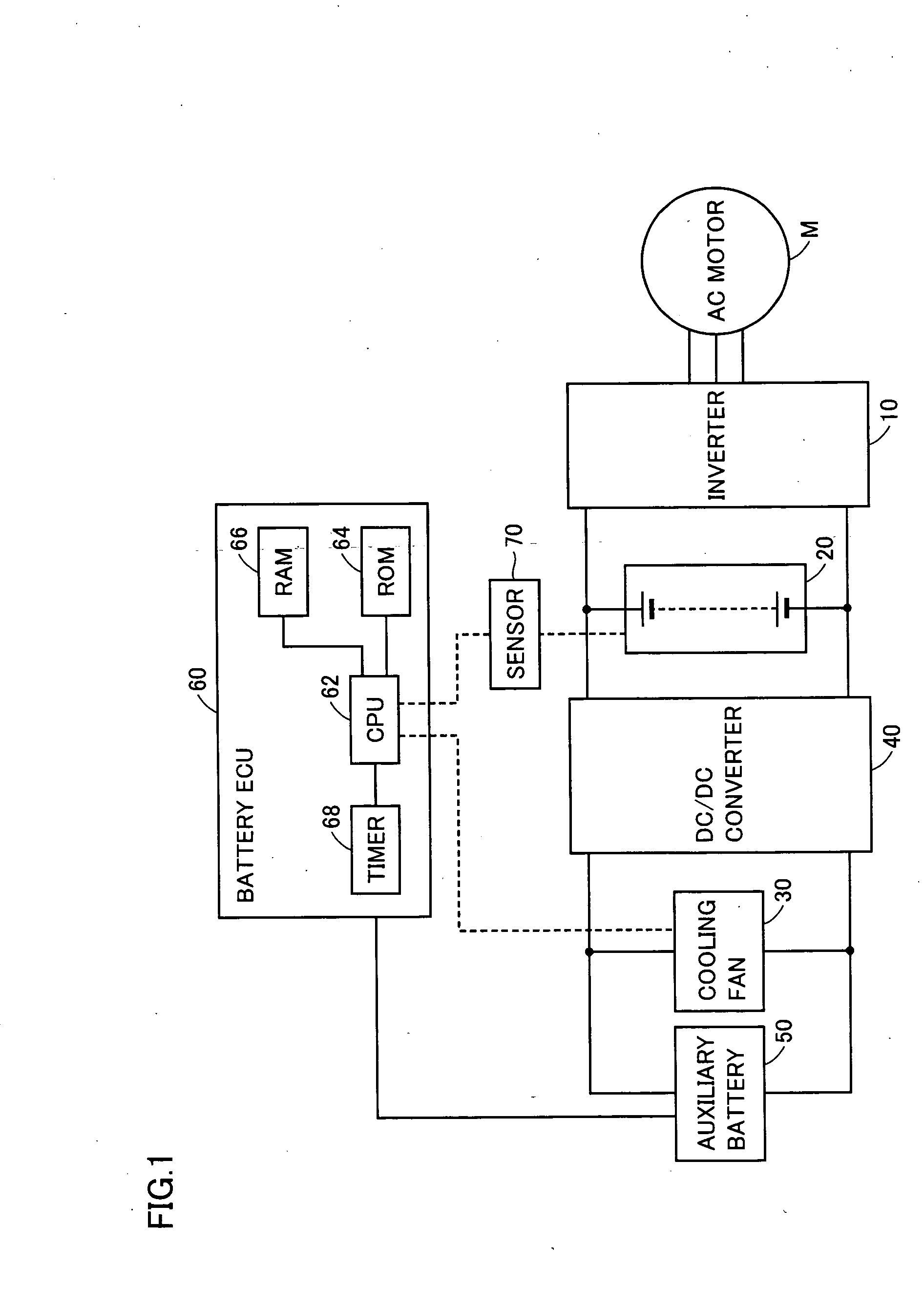
[0058]FIG. 1 is a schematic block diagram of a motor driving device according to the embodiment of the present invention.

[0059] Referring to FIG. 1, the motor driving device includes an inverter 10 supplying an AC motor M with electric power, a main battery 20 supplying electric power through inverter 10, a cooling fan 30, a DC / DC converter 40, an auxiliary battery 50, and a battery ECU (Electrical Control Unit) 60 controlling charging / discharging of the battery.

[0060] AC motor M is a driving motor for producing torque for driving the driving wheels of a hybrid vehicle or an electric vehicle. Alternatively, in a hybrid vehicle, AC motor M may not be a motor that drives the driving wheels, but it may be the one that has a function of a generator driven by the ...


PUM


Abstract

After a vehicle system is actuated, a mode command unit determines that an auxiliary battery is cleared. Determining that the auxiliary battery is cleared because of loss of stored information of backup RAM, the mode command unit outputs a cooling mode command signal SI specifying a prescribed cooling mode to a fan circuit, and starts measuring a prescribed time with a timer. The fan circuit drives a fan motor with a prescribed cooling mode and detects a number of rotations of the fan motor to transmit to the mode command unit as a fan output signal. The mode command unit detects a failure of a cooling fan from a comparison result of the fan output signal and the specified prescribed cooling mode. The timer senses a lapse of the prescribed time, and the failure detection ends.

Description

[0001] This nonprovisional application is based on Japanese Patent Application No. 2004-150263 filed with the Japan Patent Office on May 20, 2004, the entire contents of which are hereby incorporated by reference. BACKGROUND OF THE INVENTION [0002] 1. Field of the Invention [0003] The present invention relates to a cooling device controlling apparatus that controls a cooling device for an electric unit mounted on a vehicle, and particularly, to a cooling device failure detecting apparatus and a cooling device failure detecting method for detecting a failure of a cooling device, and to a computer readable recording medium recording a program for causing a computer to execute detection of a failure of a cooling device. [0004] 2. Description of the Background Art [0005] Generally, in a vehicle such as an EV (Electric Vehicle) or an HV (Hybrid Vehicle), the drive power from electric energy is obtained by converting DC (Direct Current) power supplied from a main battery of high voltage t...

Claims


Application Information

Patent Timeline
Patent Type & Authority Applications(United States)
IPC IPC(8): B60L3/00B60H1/32B60L11/18F04D27/00F25B27/00G05B23/02H02J7/00H05K7/20
CPCB60L3/0023H05K7/20209B60L2260/56
Inventor ISHISHITA, TERUO
Owner TOYOTA JIDOSHA KK
Why Eureka
Try Eureka