Substrate treating apparatus
a technology of substrate and treating apparatus, which is applied in the direction of separation process, cleaning using liquids, and water treatment, can solve the problems of low working efficiency of the apparatus and often blocked filters, and achieve the effect of accurately separating and decomposing film particles
- Summary
- Abstract
- Description
- Claims
- Application Information
AI Technical Summary
Benefits of technology
Problems solved by technology
Method used
Image
Examples
embodiment 1
[0059] Embodiment 1 of this invention will be described hereinafter with reference to the drawings.
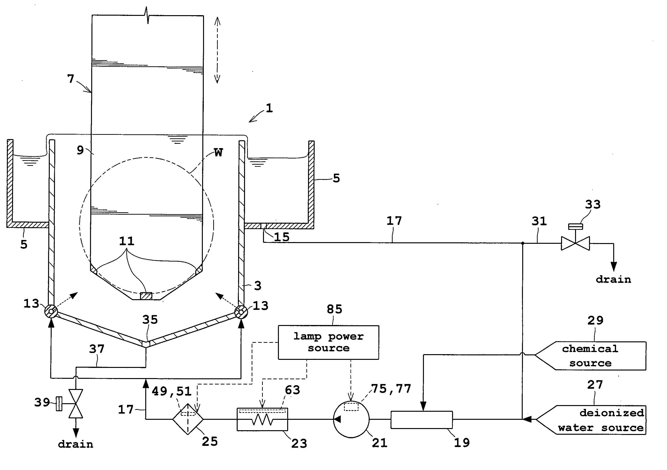
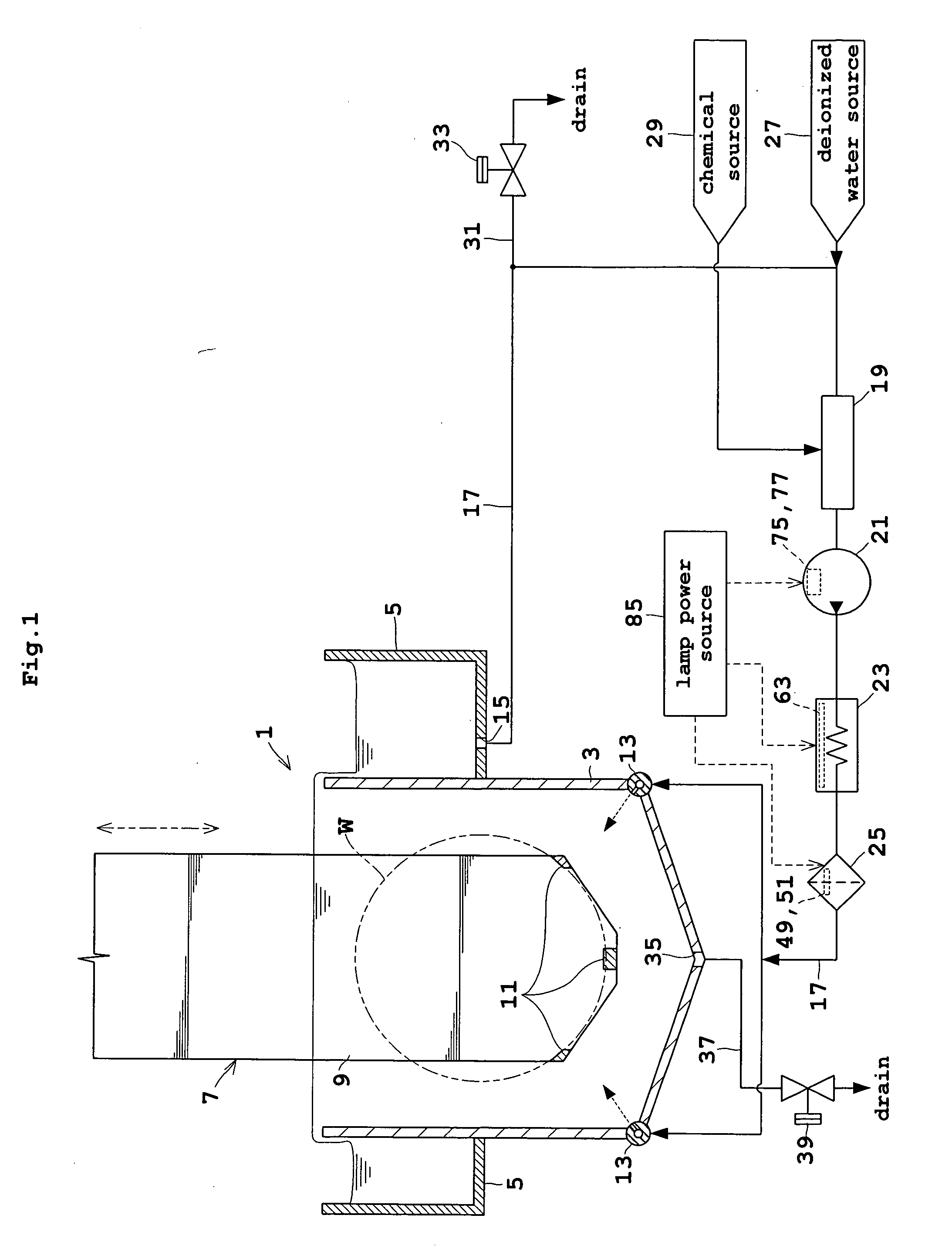
[0060]FIG. 1 is a block diagram showing an outline of a substrate treating apparatus in Embodiment 1.
[0061] A treating tank 1, which corresponds to the treating unit in this invention, includes an inner tank 3 for storing a treating solution containing sulfuric acid (H2SO4) and hydrogen peroxide solution (H2O2), and an outer tank 5 disposed around the inner tank 3 for collecting the treating solution overflowing the inner tank 3. Circular wafers W under treatment are supported by a holding mechanism 7 vertically movable between a treating position inside the inner tank 3 and a standby position above the inner tank 3. The holding mechanism 7 includes a back plate 9, and support elements 11 attached to lower positions of the back plate 9 and extending perpendicular to the plane of FIG. 1. Thus, the holding mechanism 7 is constructed for holding a plurality of wafers W at a time. The wa...
embodiment 2
[0083] Embodiment 2 of the invention will be described hereinafter with reference to FIG. 6 of the drawings. Like reference numerals will be used to identify like parts which are the same as in Embodiment 1, and will not be described again. FIG. 6 is a block diagram showing an outline of a substrate treating apparatus in Embodiment 2.
[0084] The substrate treating apparatus in Embodiment 1 described above is the batch type that treats a plurality of wafers W at a time. The substrate treating apparatus in Embodiment 2 is the single-substrate type that treats one wafer W at a time.
[0085] A treating unit 89 in this substrate treating apparatus includes a chuck 91 for holding a wafer W in horizontal posture by suction, and a scatter preventive cup 93 surrounding the chuck 91. The chuck 91 is connected at the bottom thereof to a rotary shaft of a rotary motor 95. The scatter preventive cup 93 includes a drain zone 97 shaped annular in plan view, and defining a drain port 99. The drain p...
embodiment 3
[0088] Embodiment 3 of the invention will be described hereinafter with reference to FIG. 7 of the drawings.
[0089]FIG. 7 is a block diagram showing an outline of a substrate treating apparatus in Embodiment 3.
[0090] A treating tank 1 includes an inner tank 3 for storing a treating solution containing sulfuric acid and hydrogen peroxide solution, and an outer tank 5 disposed around the inner tank 3 for collecting the treating solution overflowing the inner tank 3. Circular wafers W under treatment are supported by a holding mechanism 7 vertically movable between a treating position inside the inner tank 3 and a standby position above the inner tank 3. The holding mechanism 7 includes a back plate 9, and support elements 11 attached to lower positions of the back plate 9 and extending perpendicular to the plane of FIG. 7. Thus, the holding mechanism 7 is constructed for holding a plurality of wafers W at a time. The wafers W have surfaces thereof coated with photoresist film, for ex...
PUM
| Property | Measurement | Unit |
|---|---|---|
| Temperature | aaaaa | aaaaa |
| Pressure | aaaaa | aaaaa |
Abstract
Description
Claims
Application Information
 - R&D
- Intellectual Property
- Life Sciences
- Materials
- Tech Scout
- Unparalleled Data Quality
- Higher Quality Content
- 60% Fewer Hallucinations
Browse by: Latest US Patents, China's latest patents, Technical Efficacy Thesaurus, Application Domain, Technology Topic, Popular Technical Reports.
© 2025 PatSnap. All rights reserved.Legal|Privacy policy|Modern Slavery Act Transparency Statement|Sitemap|About US| Contact US: help@patsnap.com


