Battery pack

a battery pack and battery technology, applied in the field of batteries, can solve the problems of limited number of apparatuses connectable with this kind of mobile information terminal, and achieve the effects of increasing the thermal coupling of the battery, increasing the temperature-based power control of the battery, and ensuring the safety of the battery pack

Active Publication Date: 2005-11-24
MURATA MFG CO LTD
View PDF3 Cites 7 Cited by
  • Summary
  • Abstract
  • Description
  • Claims
  • Application Information

AI Technical Summary

Benefits of technology

[0020] The above configuration of the battery pack according to another aspect of the present invention provides the resin-formed body, which holds, along the battery, the first wiring substrate having the electronic components surface-mounted on the battery side-face thereof and the second wiring substrate having the electronic components surface-mounted on the opposite face to the battery side-face of the first wiring substrate while having no surface-mounted electronic component on the battery side-face thereof. This allows the first wiring substrate to hold the mounted components so as to be in the vicinity of the battery and thus also allows these electronic components to have an increased thermal coupling with the battery. In addition, this also allows the first wiring substrate to appropriately select a mounted component to be mounted thereon so that, even when the mounted component is held in close contact with the battery, the first wiring substrate may ensure a sufficient spatial distance corresponding to the mounted component by adjusting a soldering position or the like thereon, to which the mounted component is soldered. On the other hand, the second wiring substrate may be held in extremely close contact with the battery. This allows the electronic components surface-mounted on the first wiring substrate to serve as the control circuit for controlling the power of the battery, thereby increasing a battery temperature-based power control and also ensuring a safety of the battery pack enabled by the above sufficient spatial distance. On the other hand, the second wiring substrate has the input / output circuit for the IC card or the like, which has relatively few safety requirements as compared with the control circuit. This allows the second wiring substrate to utilize a sufficient space along the battery such that the space may receive the input / output circuit or the like, thereby providing a minimized increase of a thickness of the second wiring substrate. As a result, the battery pack of the present invention may have a minimized increase of the entire thickness thereof, thereby serving also as the interface such as the interface for the IC card.
[0021] In addition, the first and second wiring substrates may be connected together to allow a connector, whose function is to be a mediator for an output of the power, to be additionally used for a connection between the second wiring substrate and the mobile information terminal, thereby allowing the entire configuration of the battery pack of the present invention to be simplified.
[0022] In addition, the connection of the second wiring substrate to the mobile information terminal through the first wiring substrate also allows the battery pack of the present invention to have simplified internal connections.
[0023] The spacer serving as the injection-molded body has the openings on portions thereon which correspond to the electronic components mounted on the second wiring substrate, thereby allowing the battery pack of the present invention to have a proportional reduction of the entire thickness thereof.

Problems solved by technology

A downsizing of this kind of mobile information terminal, however, involves a disadvantage of a limitation on a space, in which interfaces connectable with various apparatuses are received, resulting in a limited number of apparatuses connectable with this kind of mobile information terminal.

Method used


Image

  • Battery pack
  • Battery pack
  • Battery pack

Examples


first embodiment

[0034] A configuration of a battery pack according to the present invention will now be described.

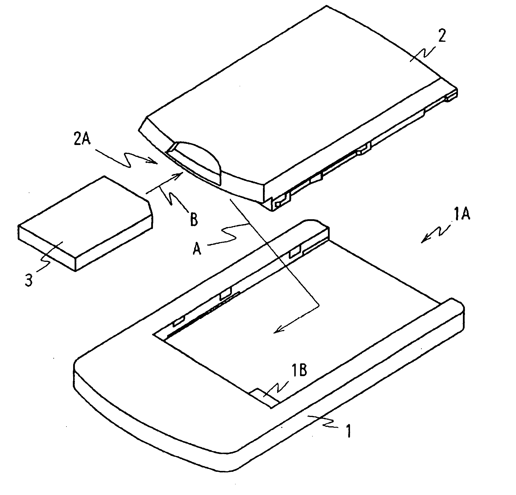
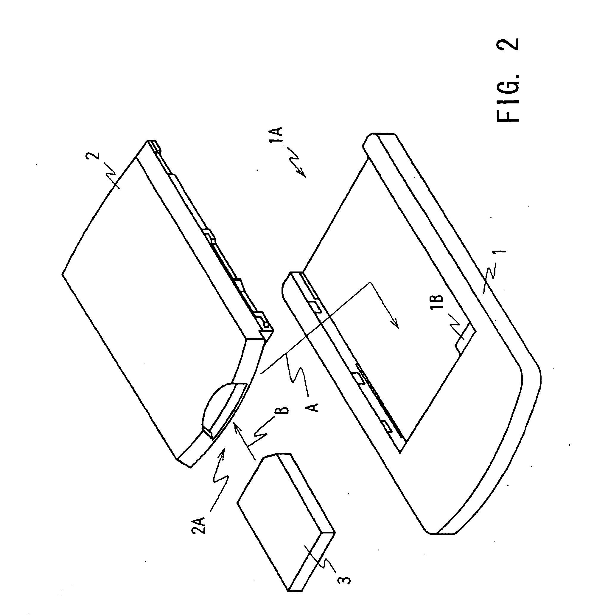
[0035]FIG. 2 is a perspective view of a mobile information terminal 1 according to the first embodiment of the present invention as seen from a back face side thereof. The mobile information terminal 1 is a PDA (personal digital assistant), which has, on a surface thereof, a liquid crystal display panel, and which also has, on the surface or the like thereof, various operators and an interface. These operators and interface allow the mobile information terminal 1 to be connected to a personal computer or the like, for instance, so as to upload information stored in the personal computer for viewing or to allow the mobile information terminal 1 to download various pieces of information stored therein to the personal computer.

[0036] The mobile information terminal 1 has, on a back face thereof, a recess section 1A for receiving a battery pack 2 detachably. The recess section 1A has, on a...

second embodiment

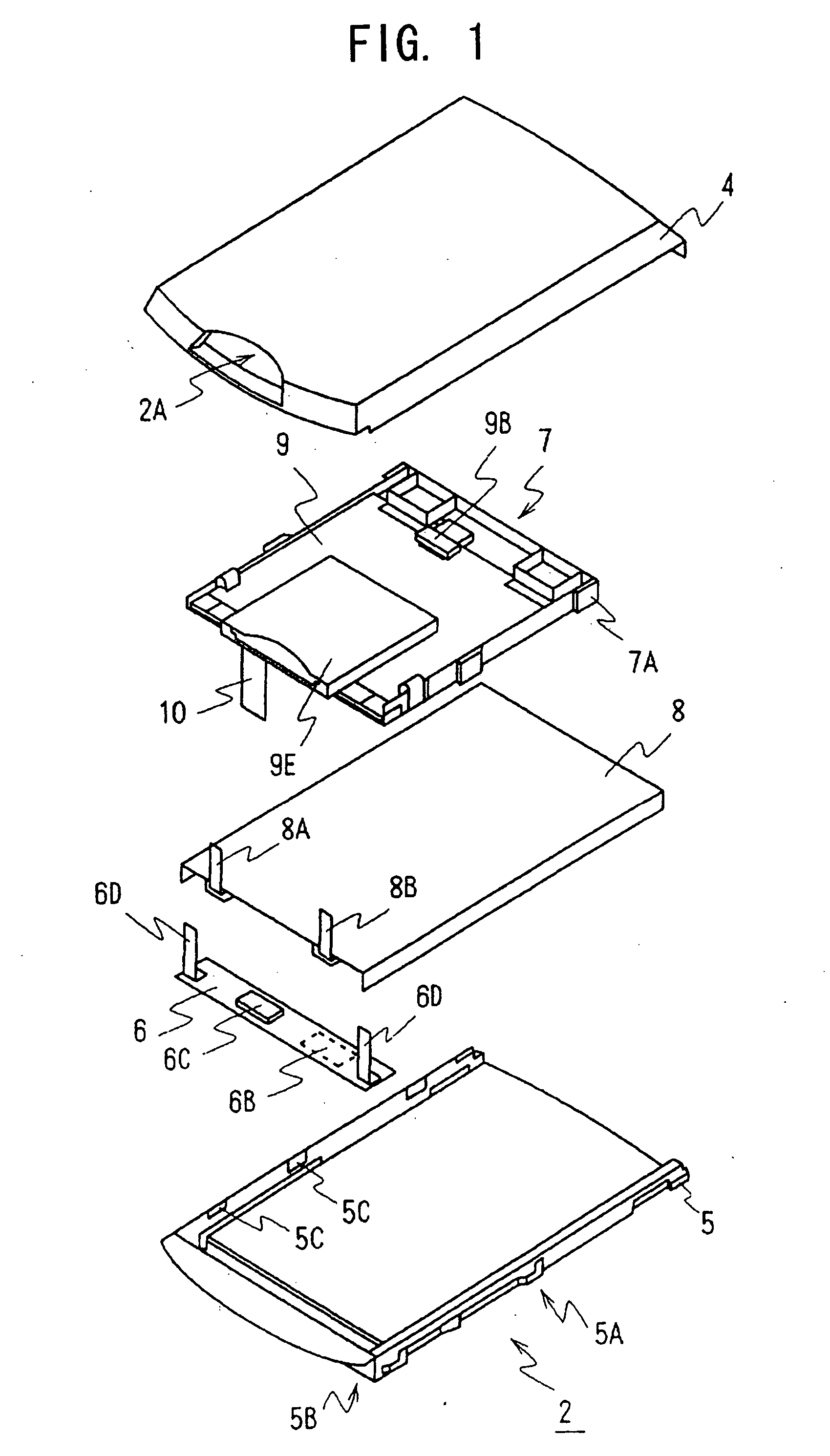
[0063] According to the present invention, a spacer 27 is formed by subjecting a resin to an injection molding and is positioned by the recess sections 5C provided on the lower casing 5 so as to be held in place on an inner wall surface of the exterior housing composed of the upper casing 4 and the lower casing 5. In other words, the spacer 27 is placed on the lower casing 5 such that projecting sections 27A are provided on an outer wall surface so as to correspond to the recess sections 5C of the lower casing 5 and the recess sections 5C engage with the projecting sections 27A so as to prevent the battery pack 22 from being dislocated in the longitudinal direction thereof and to provide a predetermined space between the lower casing 5 and the spacer 27.

[0064] Referring to FIG. 7, the spacer 27 has the projecting sections 27A, bar-shaped side plates 27B extending along the inner wall surface of the lower casing 5 and bottom plates 27C for connecting the side plates 27B with each oth...


PUM

PropertyMeasurementUnit
poweraaaaaaaaaa
thicknessaaaaaaaaaa
driving forceaaaaaaaaaa

Abstract

There is disclosed a battery pack, which has a plate-shaped resin-formed body to divide an internal space of the battery pack into at least two spaces in a thickness direction thereof, so that a battery is received in a first internal space, while a wiring substrate having a control circuit packaged thereon is placed in a second internal space, thereby allowing the battery pack to hold an input/output circuit or the like of a memory card securely in a limited space in the battery pack, while ensuring that a sufficient insulation is provided to the battery, when the battery pack is used for PDA'S, for instance.

Description

CROSS REFERENCES TO RELATED APPLICATIONS [0001] The present document is based on Japanese Priority Documents JP 2001-374039 and JP 2001-374086, both filed in the Japanese Patent Office on Dec. 7, 2001, the entire contents of which being incorporated herein by reference. BACKGROUND OF THE INVENTION [0002] 1. Field of the Invention [0003] This invention relates to a battery pack, which may be used for PDAs (Personal Digital Assistants), for instance. More specifically, the present invention relates to a battery pack having a plate-shaped resin-formed body for dividing an internal space of the battery pack into two spaces in a thickness direction so that a battery is received in one internal space, and a wiring substrate having a control circuit mounted thereon is placed in the other internal space, thereby providing the battery pack, which may securely hold an input / output circuit or the like for a memory card in a limited space in the battery pack, while ensuring that a sufficient in...

Claims


Application Information

Patent Timeline
Patent Type & Authority Applications(United States)
IPC IPC(8): H01M2/02H01M10/04H01M10/42H01M10/44H05K1/14
CPCH01M2/0207H01M10/0436H01M10/42H05K1/14H01M10/4257H01M10/44H01M10/425Y02E60/10Y02P70/50
Inventor SAKUMA, KAZUHIKOANZAI, CHIAKI
Owner MURATA MFG CO LTD
Why Eureka
Try Eureka