Ocean bottom seismometer package with distributed geophones

Active Publication Date: 2005-11-24
MAGSEIS FF LLC
View PDF26 Cites 27 Cited by
  • Summary
  • Abstract
  • Description
  • Claims
  • Application Information

AI Technical Summary

Benefits of technology

[0018] Another added benefit of the concept of this invention is that in summing the outputs (or weighted outputs as the case may be) of multiple geophones within a single casin

Problems solved by technology

These factors may include 1) near surface waves which may cause a “rocking” motion of the unit thereby producing undesirable energy, 2) shear wave energy which may cause a “rocking” motion of the unit related to the package height and the shear force acting on the base of the unit against the resistance of the water, all of which combine to produce undesirable cross coupling shear energy (it appears that softer sediments tend to accentuate this type of distortion), 3) ocean currents which can produce extraneous energy and noises, and 4) various random noises such as sea creature noises, natural noises or “manmade” noises, all of which can contaminate the desired true responses.
This also has the result of limiting the position of other components around the geophones.
One drawback to this particular design is that the geophone package is not coupled directly to the ocean floor.
Rather, any seismic signal recorded by the geophone

Method used


Image

  • Ocean bottom seismometer package with distributed geophones
  • Ocean bottom seismometer package with distributed geophones
  • Ocean bottom seismometer package with distributed geophones

Examples


Embodiment Construction

[0026] In the detailed description of the invention, like numerals are employed to designate like parts throughout. Various items of equipment, such as fasteners, fittings, etc., may be omitted to simplify the description. However, those skilled in the art will realize that such conventional equipment can be employed as desired.

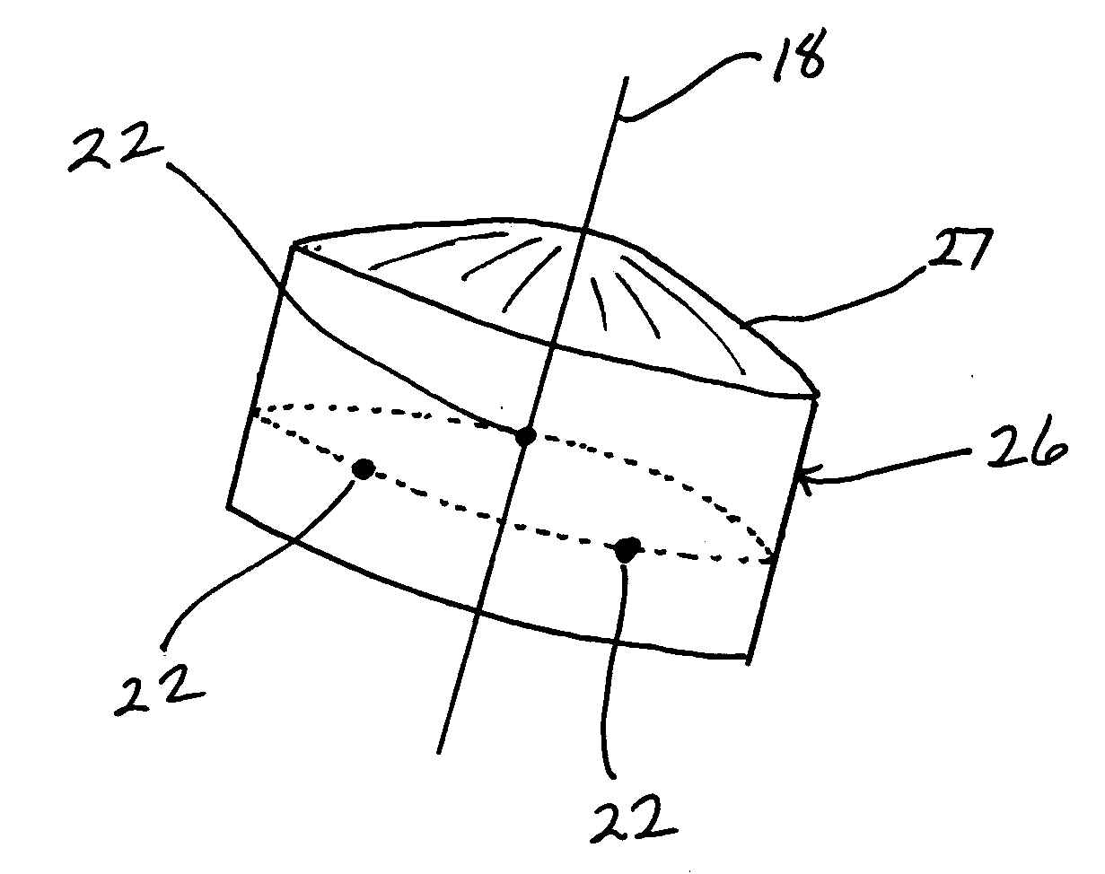
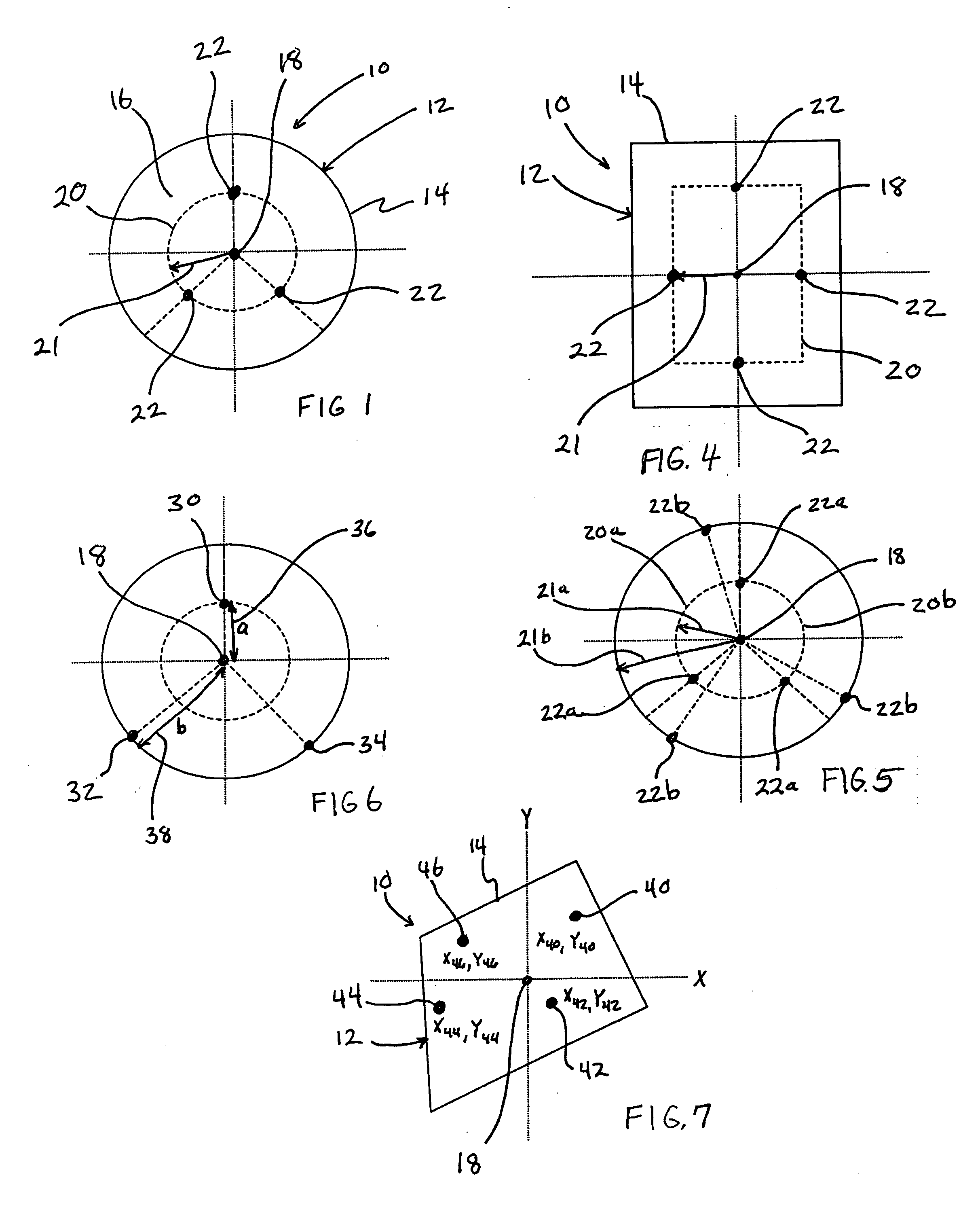
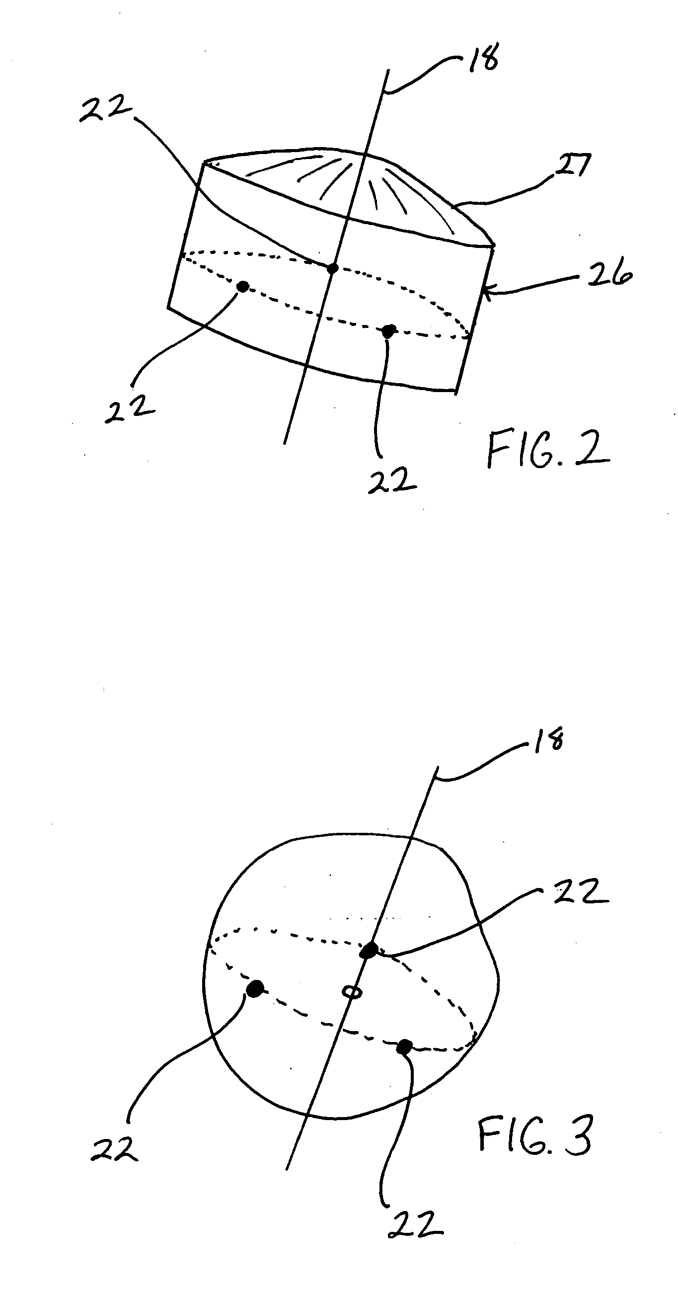
[0027] With reference to FIG. 1, there is shown a seismic data collection unit or pod 10 of the invention. Pod 10 is comprised of a case 12 having a wall 14 defining an internal compartment 16. Case 12 is further characterized by a vertical axis 18 passing through the center of gravity and a geophone placement circumference 20 of a selected linear offset distance 21. Disposed within compartment 16 on circumference 20 are three distributed geophone / geophone packages 22 which are secured inside compartment 16 such that pod 10 functions as a rigid structure to which geophones 22 are attached. Utilizing multiple distributed geophones symmetrically positioned as ...


PUM


Abstract

A seismic data collection unit having multiple separate geophones/geophone packages positioned in a housing wherein the geophones are offset from a vertical axis so that summing of the geophones' respective outputs minimizes certain noise in the unit's output. Specifically, the offset geophones are physically positioned or mathematically configured so as to be symmetrical about a selected vertical axis in order to cancel out certain noise in a seismic signal. The particular placement of the geophones within the housing is preferably selected so that the vertical axis around which the geophones are positioned passes through the center of gravity of the unit.

Description

BACKGROUND OF THE INVENTION [0001] The present invention relates to the field of seismic exploration. More particularly, the invention relates to an apparatus for seismic exploration, and most particularly to marine seismic exploration utilizing ocean bottom seismometer systems. [0002] Seismic exploration systems placed on the ocean bottom floor have been in use for many years. These devices are typically referred to as “OBC” (Ocean Bottom Cabling) or “OBS” (Ocean Bottom Seismometer) systems. The prior art has centered on three main groups of ocean bottom apparatus to measure seismic signals at the seafloor. The first type of apparatus is an OBC system, similar to the towed streamer, which consists of a wire cable that contains geophones and / or hydrophones and which is laid on the ocean floor, where the detector units are interconnected with cable telemetry. [0003] A second type of recording system is comprised of OBS units, each of which has a seismic sensor and electronics package...

Claims


Application Information

Patent Timeline
IPC IPC(8): G01V1/16G01V1/20G01V1/38
CPCG01V1/3808
Inventor RAY, CLIFFORD H.FISSELER, GLENN D.
Owner MAGSEIS FF LLC
Why Eureka
Try Eureka