

Ultrasonic reactor and process for ultrasonic treatment of materials
a technology of ultrasonic reactor and material, applied in the direction of mechanical vibration separation, grain treatment, transportation and packaging, etc., can solve the problems of low energy output, inconvenient operation, and inability to reliably opera
- Summary
- Abstract
- Description
- Claims
- Application Information
AI Technical Summary
Benefits of technology
Problems solved by technology
Method used
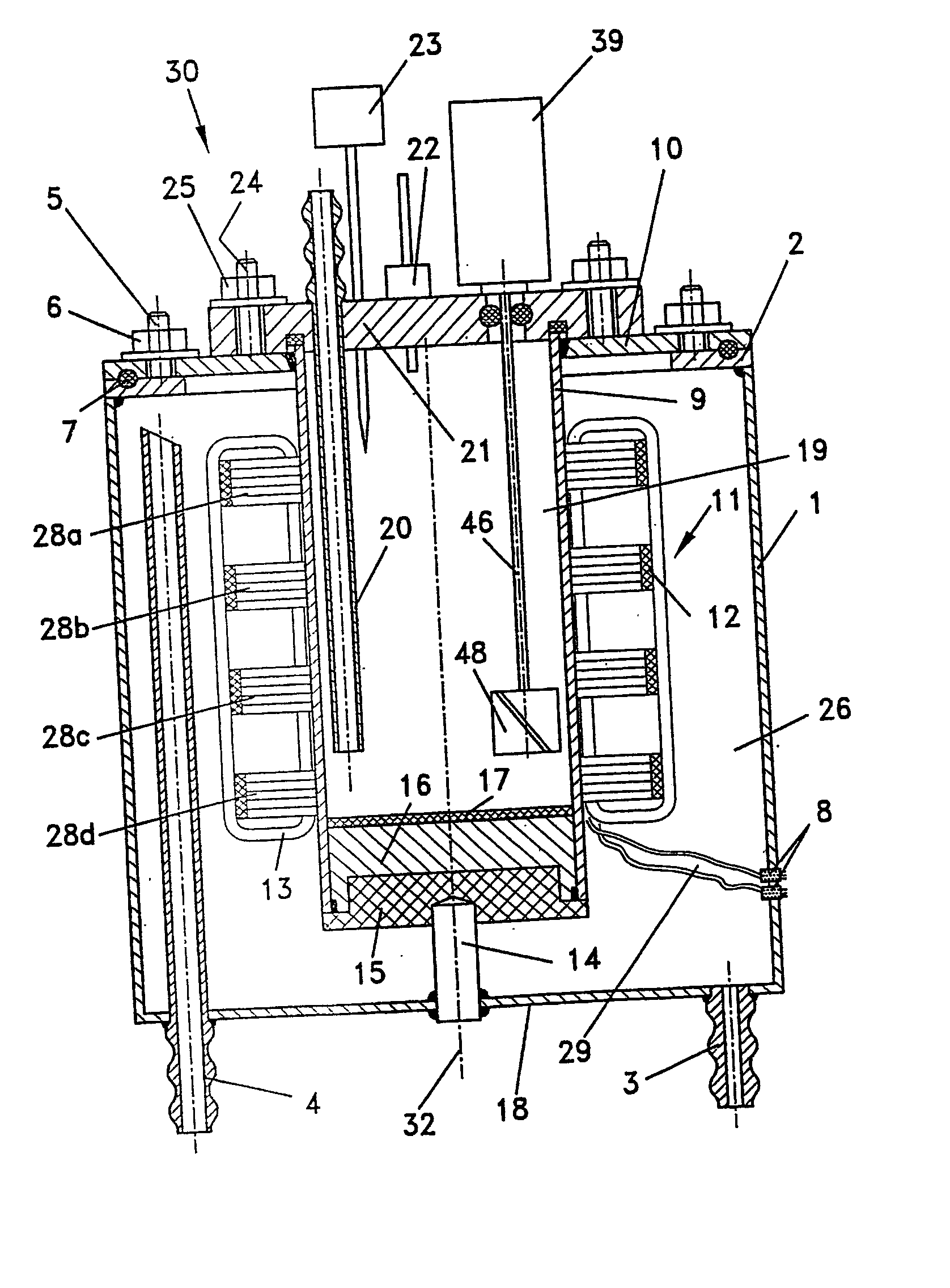
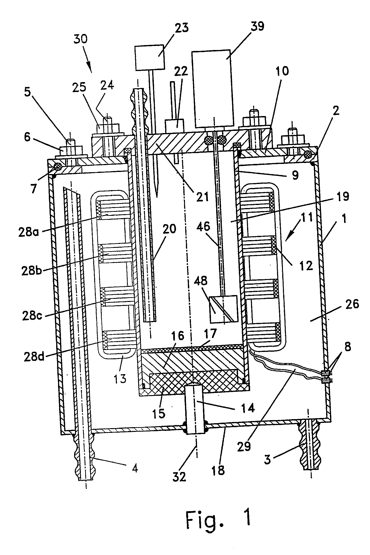
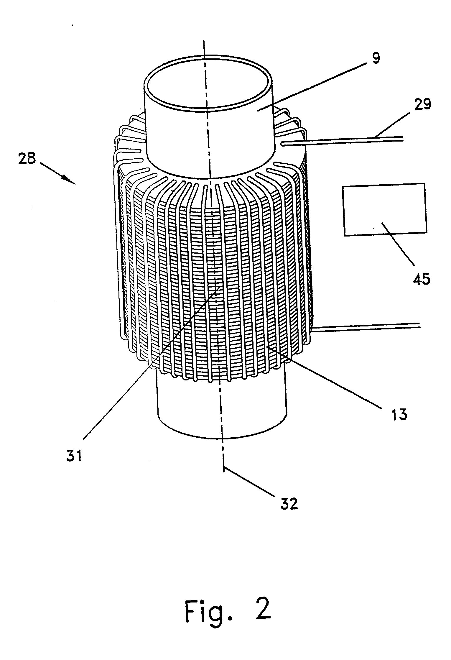
Image

Examples
example 1
Ultra-Fine Grinding
[0094] 85 g of silver particles are mixed with 780 ml of deionized water. The suspension is fed into a 1 L chamber, and is treated for a period of 3 hours at a pressure of 3.5 atmospheres with an influx of ultrasonic energy having a power of 3 kW, wherein the temperature within the process chamber is 44° C.
[0095] The following is the particle size distribution, in microns, wherein the subscript refers to the percentage of total particles having a size equal to or less than the listed value:
d10d50d90Initial7.926.154.3Final0.090.140.2
example 2
Ultra-Fine Grinding
[0096] 1000 g of silica particles for use in glazed coatings are added to 4600 ml of deionized water. The suspension is fed into a 5 L chamber, and is treated for a period of 90 minutes at a pressure of 3.2 atmospheres with an influx of ultrasonic energy having a power of 4.6 kW, wherein the temperature within the process chamber is 42° C.
[0097] The following is the particle size distribution in microns, wherein the subscript refers to the percentage of total particles having a size equal to or less than the listed value:
d10d50d90Initial0.81.95.9Final0.090.61.5
example 3
Ultra-Fine Grinding
[0098] 600 g of ceria particles (CeO2) needed for Chemical Mechanical Planarization (CMP) are added to 4600 ml of deionized water. The suspension is fed into a 4.5 L chamber, and is treated for a period of 60 minutes at a pressure of 3.0 atmospheres with an influx of ultrasonic energy having a power of 4.6 kW, wherein the temperature within the process chamber is 32° C.
[0099] The following is the particle size distribution in microns, wherein the subscript refers to the percentage of total particles having a size equal to or less than the listed value:
d10d50d90Initial0.63.248.93Final0.150.240.65
PUM
| Property | Measurement | Unit |
|---|---|---|
| Fraction | aaaaa | aaaaa |
| Fraction | aaaaa | aaaaa |
| Thickness | aaaaa | aaaaa |
Abstract
Description
Claims
Application Information