
Tunable superconducting RF cavity

a superconducting, cavity technology, applied in the direction of resonators, antennas, electricly long antennas, etc., can solve the problems of large and complex machines, less effective coupling energy into the particle to achieve the acceleration of the desired particle, and limit the precision they can achieve. , to achieve the effect of high speed, low power and high for

Inactive Publication Date: 2005-11-24
ENERGEN
View PDF5 Cites 7 Cited by
  • Summary
  • Abstract
  • Description
  • Claims
  • Application Information

AI Technical Summary

Benefits of technology

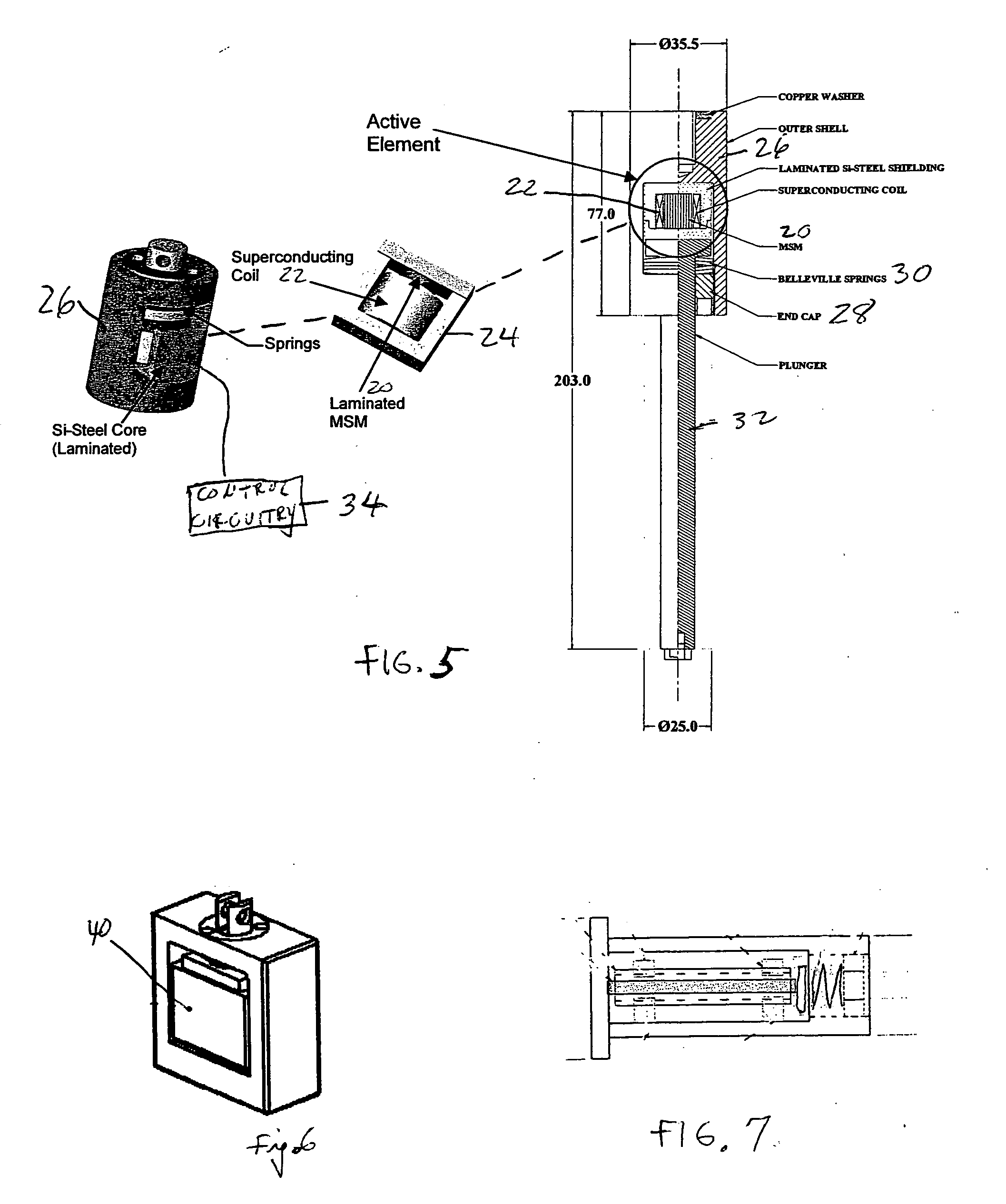
[0013] The use of magnetostrictive materials results in a compact, high force, low power, high speed actuator. For the same size, the magnetostrictive actuator will produce larger forces than can conventional actuators. Magnetostrictive actuators are also very high speed with response time on the order of microseconds. Such actuators also provide backlash-free precision motion. The simple construction and controls result in actuators that can be readily retrofitted to existing particle accelerator systems. Finally, magnetostrictive actuators provide reliable, robust operation at cryogenic temperatures and in vacuum environments.

Problems solved by technology

These large and complex machines use radio frequency (RF) energy to accelerate sub-atomic particles at speeds approaching the speed of light.
This vibration causes a shift in the resonant frequency of the cavity making it less effective in coupling energy into the particle to achieve a desired particle acceleration.
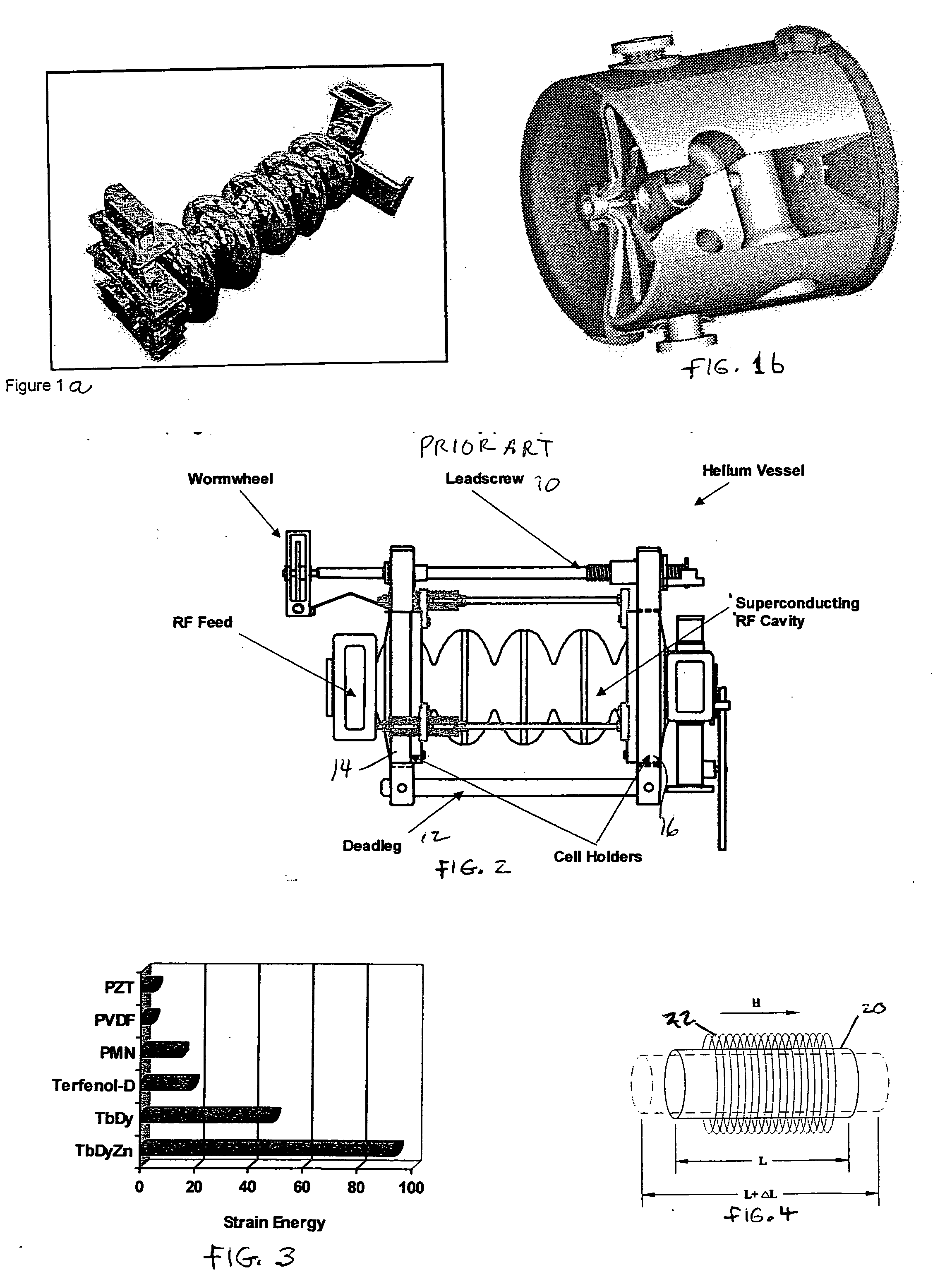
Prior art cavity tuners such as that shown in FIG. 2 have disadvantages because they utilize conventional actuators such as motors, solenoids and hydraulic actuators.
Such conventional actuators have a significant stroke but there is a limit to the precision they can achieve.
They are also impractical for applications in which a large force output is needed because they tend to become bulkier and consume large amounts of power.
Further, such mechanical actuators present problems at cryogenic temperatures.
Cavity tuners based on piezoelectric actuators are also known but are proving to be inadequate to the task.
Although piezoelectric actuators can respond in the time required, they have very limited stroke at cryogenic temperatures.
This high voltage is not compatible with vacuum and cryogenic systems.
This incompatibility results from breakdown and the damage that can occur to the vacuum integrity of a cryostat from flashovers in the actuators.
For long term operation, there is concern that the layers will delaminate causing degradation in the actuator performance with time.

Method used


Image

  • Tunable superconducting RF cavity
  • Tunable superconducting RF cavity
  • Tunable superconducting RF cavity

Examples


Embodiment Construction

[0022] Some of the theory on which the present invention is based will now be described. While overall strain capability and force density are important in actuating material selection, what is important for the acoustic control applications disclosed herein is the ability of the material to absorb and remove acoustic energy from its surroundings. For the applications set forth in this specification, the correct figure of merit is strain energy given by the following equation:

E=½ YSSS2max

wherein E is the strain energy, YSS is elastic modulus, and Smax is the saturation magnetostrictive strain of a given material. FIG. 3 compares the strain energy for several actuator materials. This figure shows that magnetostrictors such as TbDyZn and Terfenol-D have significantly higher strain energy than PZT, the most commonly used piezoelectric actuator material. Thus, for vibration damping for a particle accelerator, magnetostrictive actuators are more efficient. This improved efficiency tra...


PUM


Abstract

Tunable RF cavity. The cavity includes a magnetostrictive material coupled to the cavity and a magnetic coil configured to impress a magnetic field on the magnetostrictive material. Control circuitry energizes the magnetic coil to control the shape of the magnetostrictive material, thereby to control the length of the cavity to tune its resonant frequency.

Description

BACKGROUND OF THE INVENTION [0001] This invention relates to superconducting RF cavities and more particularly to cavity tuners able to adjust the resonant frequency of a cavity with fast response time. [0002] Large research particle accelerators are used to study the fundamental nature of matter and attempt to understand the origins of the universe. These large and complex machines use radio frequency (RF) energy to accelerate sub-atomic particles at speeds approaching the speed of light. Special accelerating structures known as RF cavities are used to enable the particles to absorb as much of the RF energy as possible thereby increasing their speed and energy. Recently, more efficient accelerating structures have been made using superconducting cavities. There are two types of superconducting RF cavities commonly used in particle accelerators depending on the scientific goals to be achieved—elliptical cavities and spoke cavities. The efficiency of superconducting cavities derives ...

Claims


Application Information

Patent Timeline
Patent Type & Authority Applications(United States)
IPC IPC(8): H01P7/06H04B1/04H04B1/40
CPCH01P7/06
Inventor JOSHI, CHANDRASHEKHAR H.MAVANUR, ANILTAI, CHIU-YING
Owner ENERGEN
Learn More