Concrete foundation wall with a low density core and carbon fiber and steel reinforcement

a low density core, carbon fiber and steel reinforcement technology, applied in the direction of foundation engineering, building components, construction, etc., can solve the problems of high cost, inability to meet the requirements of construction, and many of the previously used building panels are prone to cracks and other damage, and achieve high insulating properties, high strength, and cost-effective manufacturing

Inactive Publication Date: 2005-12-01
OLDCASTLE PRECAST
View PDF99 Cites 15 Cited by
  • Summary
  • Abstract
  • Description
  • Claims
  • Application Information

AI Technical Summary

Benefits of technology

[0011] It is one aspect of the present invention to provide a composite wall panel that has superior strength, high insulating properties, is lightweight for transportation and stacking purposes and is cost effective to manufacture. Thus, in one embodiment of the present invention, a substantially planar insulative core with interior and exterior surfaces is positioned between concrete panels that are reinforced with carbon fiber grids positioned substantially adjacent to the insulative core. In a preferred embodiment of the present invention, the interior layer of concrete is comprised of a low-density concrete. Furthermore, as used herein, insulative core may comprise any type of material that is thermally efficient and has a low heat transfer coefficient. These materials may include, but are not limited to, Styrofoam®-type materials such as expanded polystyrenes, extruded polystyrenes, extruded polypropylene, polyisocyanurate, combinations thereof and other materials, including wood materials, rubbers, and other materials well known in the construction industry.

Problems solved by technology

Previous attempts to provide these types of building panels have failed due to the expensive transportation costs and less than ideal insulative and thermal conductivity properties associated with prefabricated concrete wire-reinforced products.
Further, due to the brittle nature of concrete, many of the previously used building panels are prone to cracks and other damage during transportation.
The relatively large weight per square foot of building panels of the prior art has resulted in high expenses arising not only from the amount of materials needed for fabrication, but also the cost of transporting and erecting the modules.
Module weight also places effective limits on the height of structures, such as stacked modules e.g., due to load limitations of the building foundations, footings and / or lowermost modules.
Furthermore, there is substantial fabrication labor expense that can arise from design, material, and labor costs associated with providing and placing reinforcement materials.
In some previous approaches, panels were required to be specially designed and cast so as to include any necessary openings, requiring careful planning and design, thus increasing costs due to the special, non-standard configuration of such panels.
Such post-casting procedures such as cutting, particularly through the thick and / or steel-reinforced panels as described above, is a relatively labor-intensive and expensive process.
In many processes for creating openings, there is a relatively high potential for cracking or splitting of the panel or module.
One other problem associated with metallic wire or bar materials used in conjunction with concrete is the varying rates of expansion and contraction.
Thus, with extreme heating and cooling the embedded metallic materials tend to separate from the concrete, thus creating cracks which may lead to exposure to moisture and the eventual degradation of both the concrete and wire reinforcement due to corrosion.
Although providing an advantage over homogenous concrete panels, the composite panel disclosed in the '375 patent does not provide the necessary strength and stiffness properties required during transportation and in high wind environments.
Further, the metallic wire mesh materials are susceptible to corrosion when exposed to water during fabrication, and have poor insulative qualities due to the high heat transfer properties of metallic wire.
Thus, the panels disclosed in the '375 patent may be more susceptible to failure when exposed to stresses during transportation, assembly or subsequent use.
Unfortunately, the insulative properties of this invention are relatively poor due to the physical nature of the concrete and steel.
Further, the excessive weight of the panels and inherent problems associated with transportation, stacking, etc. are present.
Previously known prefabricated building panels have also not been found to have sufficient tensile and compressive strength when utilizing only concrete insulative foam materials or wire mesh.

Method used


Image

  • Concrete foundation wall with a low density core and carbon fiber and steel reinforcement
  • Concrete foundation wall with a low density core and carbon fiber and steel reinforcement
  • Concrete foundation wall with a low density core and carbon fiber and steel reinforcement

Examples


Embodiment Construction

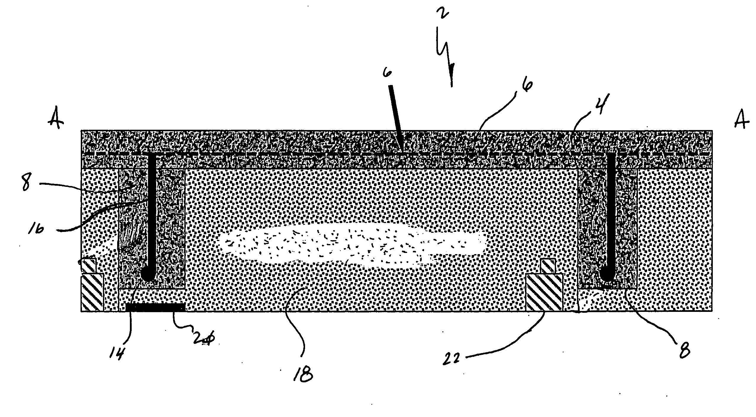
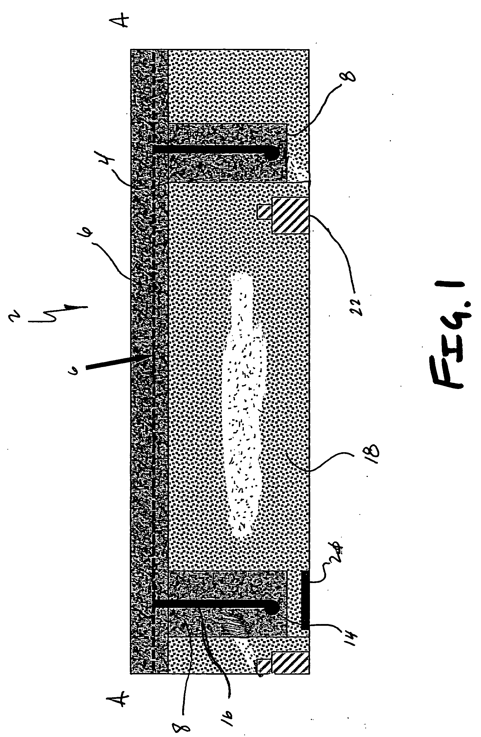
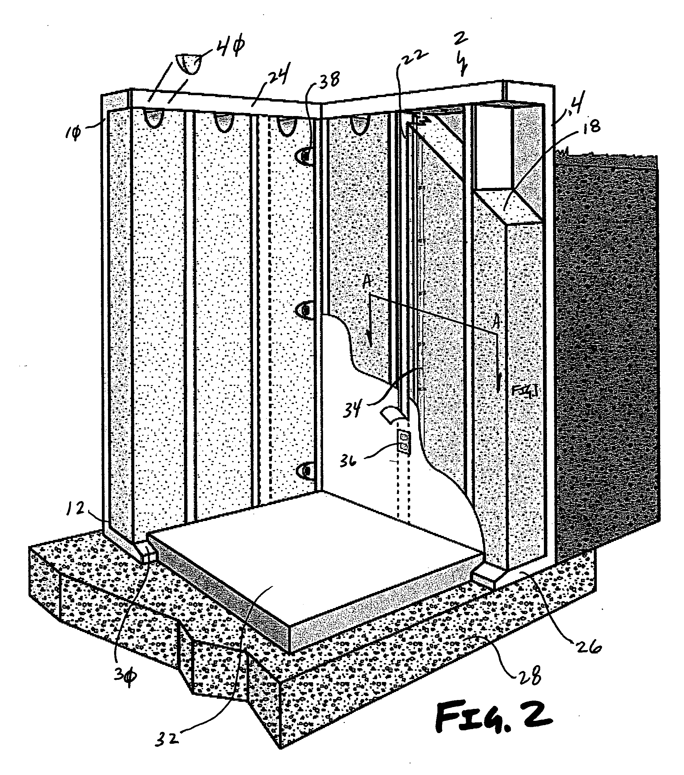
[0038] Referring now to FIGS. 1-9, one embodiment of an insulated foundation wall panel 2 is shown. More specifically, an insulated foundation panel 2 is provided that includes an exterior face wall 4 with one or more embedded carbon fiber strips 6. Interconnected to the exterior face wall 4 are a plurality of reinforcing ribs 8 running generally from an upper edge 10 to a lower edge 12 of the foundation panel 2. Tying the ribs 8 to the foundation wall 2 are reinforcing bars 14 and carbon fiber or metallic stirrups 16. Preferably, the space between each rib 8 is filled with foam insulation 18, thus providing a foundation panel 2 that is strong, light, and that has superior insulative properties. Optionally, some embodiments of the present invention employ wood, foam or metal strips 20 running substantially the length of the ribs 8 to provide a location for nails, screws, etc. such that sheet rock or other wall finishings may be applied to the foundation panel 2.

[0039] Referring aga...


PUM


Abstract

A fabricated concrete foundation wall is provided with a plurality of insulation panels and reinforcing ribs to improve strength and reduce the density of the wall panel. The foundation wall panels are easily placed and interconnected together to quickly provide a foundation adapted to support the main walls of a home, for example. The foundation panels in one embodiment generally include a facewall that may have at least one carbon fiber band positioned horizontally therethrough to provide additional stiffness.

Description

[0001] This application is a continuation-in-part of pending U.S. patent application Ser. No. 11 / 096,705, which is a continuation-in-part of pending U.S. patent application Ser. No. 10 / 772,148, filed Feb. 3, 2004, which is a continuation-in-part of pending U.S. patent application Ser. No. 10 / 423,286, filed Apr. 24, 2003, which is a continuation-in-part of U.S. patent application Ser. No. 10 / 150,465, now U.S. Pat. No. 6,729,090, filed May 17, 2002, which is a continuation-in-part of U.S. patent application Ser. No. 10 / 093,292, now U.S. Pat. No. 6,701,683, filed Mar. 6, 2002, each of the pending applications or issued patents being incorporated by reference in their entirety herein.FIELD OF THE INVENTION [0002] The present invention relates to building components, and more specifically lightweight concrete foundation walls that are manufactured in a controlled environment and can be selectively interconnected on-site to fabricate modular buildings. BACKGROUND OF THE INVENTION [0003] D...

Claims


Application Information

Patent Timeline
Patent Type & Authority Applications(United States)
IPC IPC(8): E02D27/02E04C1/00E04C2/04E04C2/06E04C2/288E04C2/38
CPCE02D27/02E04C2/044E04C2/049E04C2/06E04C2002/046E04C2/2885E04C2/382E04C2002/045E04C2/288
Inventor MESSENGER, HAROLD G.ROTONDO, THOMAS
Owner OLDCASTLE PRECAST
Why Eureka
Try Eureka