Refrigerant-based thermal energy storage and cooling system with enhanced heat exchange capability

a technology of energy storage and refrigeration system, which is applied in the field of refrigerant-based thermal energy storage and cooling system with enhanced heat exchange capability, can solve the problems of limited success of current air conditioning units having energy storage system and difficulty in achieving high-efficiency, and achieve the effects of reducing increasing the enthalpy of refrigerant, and facilitating thermal conta

Active Publication Date: 2005-12-01
ACP THULE INVESTMENTS LLC +1
View PDF39 Cites 55 Cited by
  • Summary
  • Abstract
  • Description
  • Claims
  • Application Information

AI Technical Summary

Benefits of technology

[0007] An embodiment of the present invention may comprise a refrigerant-based thermal energy storage and cooling system comprising: a condensing unit, the condensing unit comprising a compressor and a condenser; a refrigerant management unit connected to the condensing unit, the refrigerant management unit that regulates, accumulates and pumps refrigerant; a load heat exchanger connected to the refrigerant management unit that provides cooling to a cooling load by increasing the enthalpy of the refrigerant; a tank filled with a fluid capable of a phase change between liquid and solid and containing a primary heat exchanger therein, the primary heat exchanger being connected to the refrigerant management unit that uses the refrigerant from the refrigerant management unit to cool the fluid and to freeze at least a portion of the fluid within the tank; and, a secondary heat exchanger connected to the load heat exchanger that facilitates thermal contact between the cooled fluid and the refrigerant thereby reducing the enthalpy of the refrigerant, and returns the warmed fluid to the tank.

Problems solved by technology

Current air conditioning units having energy storage systems have had limited success due to several deficiencies including reliance on water chillers that are practical only in large commercial buildings and have difficulty achieving high-efficiency.

Method used


Image

  • Refrigerant-based thermal energy storage and cooling system with enhanced heat exchange capability
  • Refrigerant-based thermal energy storage and cooling system with enhanced heat exchange capability
  • Refrigerant-based thermal energy storage and cooling system with enhanced heat exchange capability

Examples


Embodiment Construction

[0015] While this invention is susceptible to embodiment in many different forms, there is shown in the drawings and will be described herein in detail specific embodiments thereof with the understanding that the present disclosure is to be considered as an exemplification of the principles of the invention and is not to be limited to the specific embodiments described.

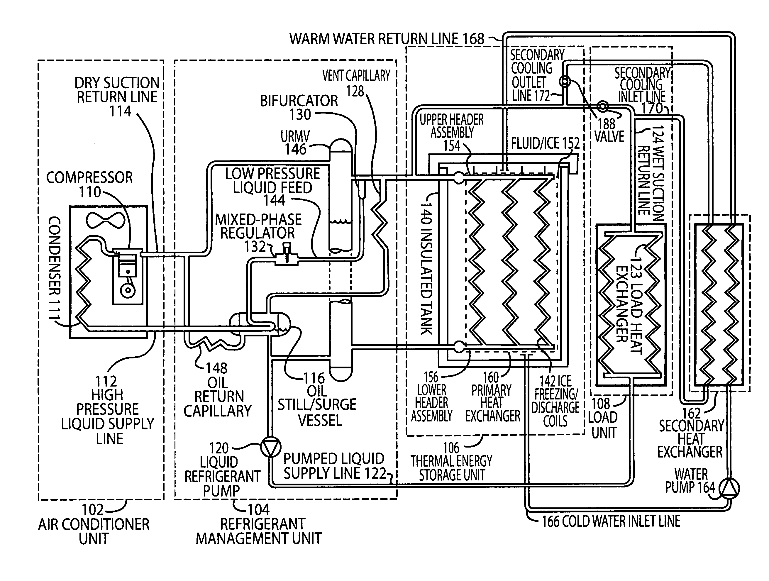
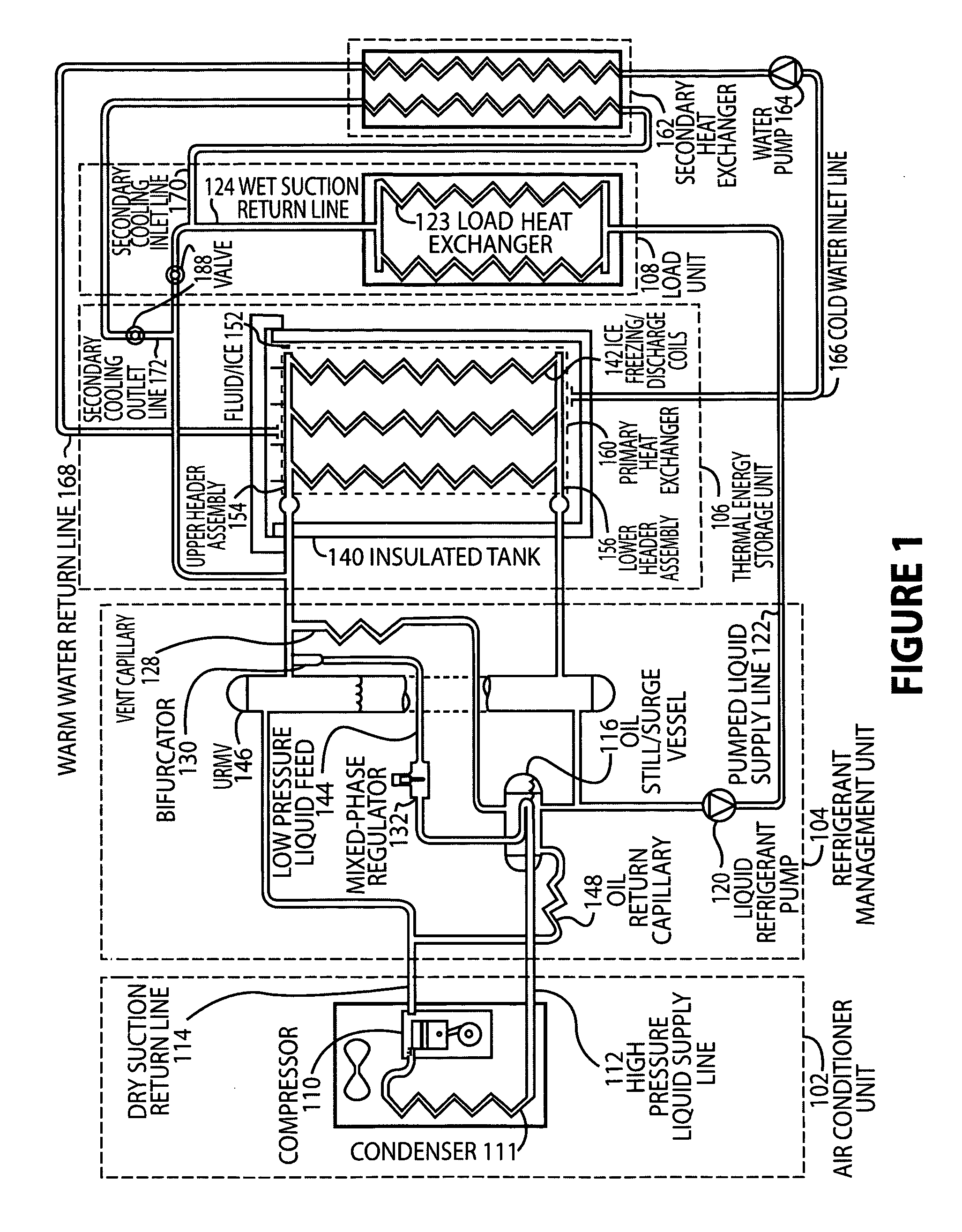
[0016] As shown in FIG. 1, an embodiment of a refrigerant-based thermal energy storage and cooling system is depicted comprising the five major components that define the system. The air conditioner unit 102 utilizes a compressor 110 and a condenser 111 to produce high-pressure liquid refrigerant delivered through a high-pressure liquid supply line 112 to the refrigeration management unit 104. The refrigeration management unit 104 is connected to a thermal energy storage unit 106 comprising an insulated tank 140 filled with fluid (i.e., water) and ice-making coils 142. The air conditioner unit 102, the refrigeration ...


PUM


Abstract

Disclosed is a method and device to increase the cooling load that can be provided by a refrigerant-based thermal energy storage and cooling system with an improved arrangement of heat exchangers. This load increase is accomplished by circulating cold water surrounding a block of ice, used as the thermal energy storage medium, through a secondary heat exchanger where it condenses refrigerant vapor returning from a load. The refrigerant is then circulated through a primary heat exchanger within the block of ice where it is further cooled and condensed. This system is known as an internal/external melt system because the thermal energy, stored in the form of ice, is melted internally by a primary heat exchanger and externally by circulating cold water from the periphery of the block through a secondary heat exchanger.

Description

CROSS REFERENCE TO RELATED APPLICATIONS [0001] This application is based upon and claims the benefit of U.S. provisional application No. 60 / 574,449, entitled “Refrigerant-Based Energy Storage and Cooling System with Enhanced Heat Exchange Capability”, filed May 25, 2004, the entire disclosure of which is hereby specifically incorporated by reference for all that it discloses and teaches.BACKGROUND OF THE INVENTION [0002] 1. Field of the Invention [0003] The present invention relates generally to systems providing stored thermal energy in the form of ice, and more specifically to ice storage cooling and refrigeration systems. [0004] 2. Description of the Background [0005] With the increasing demands on peak demand power consumption, ice storage has been utilized to shift air conditioning power loads to off-peak times and rates. A need exists not only for load shifting from peak to off-peak periods, but also for increases in air conditioning unit capacity and efficiency. Current air c...

Claims


Application Information

Patent Timeline
Patent Type & Authority Applications(United States)
IPC IPC(8): F24F5/00F25B40/02F25D3/00F25D16/00F25D17/02
CPCF24F5/0017F25B40/02Y02E60/147F25B2400/24F25D16/00F25B2400/16Y02E60/14F25B5/00F24F5/00
Inventor NARAYANAMURTHY, RAMACHANDRANHICKS, ROBERT SCOTT
Owner ACP THULE INVESTMENTS LLC
Why Eureka
Try Eureka