System for separating ammonia and carbon dioxide mixed gas

A carbon dioxide and separation system technology, applied in the preparation/separation of ammonia, carbon compounds, separation methods, etc., can solve the problems of high energy consumption, large steam consumption, and increased energy consumption of the separation system

Inactive Publication Date: 2012-09-19
BEIJING EDGEIN TECH +2
View PDF4 Cites 3 Cited by
  • Summary
  • Abstract
  • Description
  • Claims
  • Application Information

AI Technical Summary

Problems solved by technology

[0007] In order to solve the problem that the carbon dioxide separation tower in the prior art needs to consume a large amount of steam for heating and consumes a lot of energy, especially for the prior art in which the ammonia-carbon mixed gas is first absorbed with water, and then sent to the carbon dioxide separation tower in the form of an aqueous solution, In order to promote the absorption of ammonia-carbon mixed gas, it is necessary to consume energy to remove the heat of dissolution of ammonia and carbon dioxide. After the ammonia-carbon aqueous solution enters the carbon dioxide separation tower, it needs to consume energy to distill carbon dioxide out of the liquid phase to further increase the separation. The problem of system energy consumption

Method used


Image

  • System for separating ammonia and carbon dioxide mixed gas
  • System for separating ammonia and carbon dioxide mixed gas
  • System for separating ammonia and carbon dioxide mixed gas

Examples


Embodiment 1

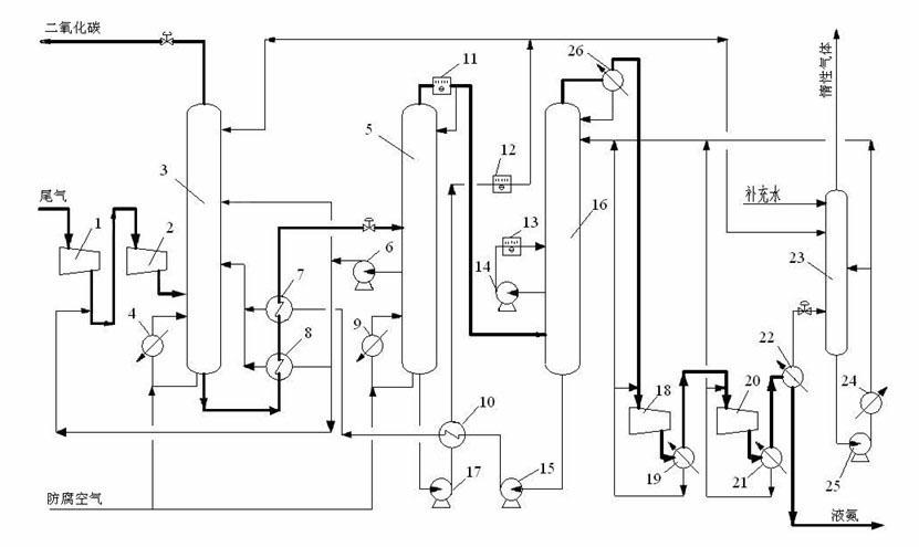
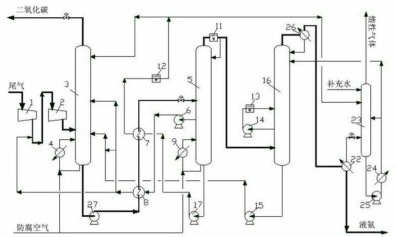
[0043] The separation system used for the mixed gas of ammonia and carbon dioxide described in this embodiment is as follows: figure 2 shown, including:

[0044] A carbon dioxide separation tower 3, a reboiler 4 is attached to the bottom of the carbon dioxide separation tower 3, and a heat exchanger 8 and a heat exchanger 7 are connected to the outlet of the ammonia-carbon aqueous solution at the bottom of the carbon dioxide separation tower 3;

[0045] Be connected with described carbon dioxide separation tower 3 and be provided with water separation tower 5, reboiler 9 is attached at the bottom of water separation tower 5, top is provided with reflux condenser 11, and described reflux condenser 11 is air cooler, and described water separation tower The middle part of 5 is provided with side line extraction pump 6, and described side line extraction pump 6 is extracted dilute ammonia-carbon aqueous solution from the side line of described water separation tower 5; Pump 17, ...

Embodiment 2

[0054] The separation system for the mixed gas of ammonia and carbon dioxide described in this embodiment is the same as that in Embodiment 1, and the separation method based on the separation system described in this embodiment is:

[0055] a. The melamine tail gas with a pressure of 4 bar is sent to the tail gas compressor section 1 for compression, the outlet pressure of the first section is 8.5 bar, the temperature rises to 234 ° C, and the temperature drops after spraying the dilute ammonia-carbon aqueous solution extracted from the side line of the water separation tower 5 to 140°C. Then it is sent to the second section 2 of the compressor for further compression, and the gas is compressed to 15bar and 223°C.

[0056] b. The compressed gas is sent to the bottom of the carbon dioxide separation tower 3, and the upper, middle and lower parts of the carbon dioxide separation tower 3 are fed into the water from the bottom of the water separation tower 5 and the dilute ammoni...

Embodiment 3

[0060] The separation system for the mixed gas of ammonia and carbon dioxide described in this embodiment is the same as that in Embodiment 1, and the separation method based on the separation system described in this embodiment is:

[0061] a. The melamine tail gas with a pressure of 4 bar is sent to the tail gas compressor section 1 for compression, the outlet pressure of the first section is 10.1 bar, the temperature rises to 257 ° C, and the temperature drops after spraying the dilute ammonia-carbon aqueous solution extracted from the side line of the water separation tower 5 to 140°C. Then it is sent to the second stage of the compressor to continue compression, and the gas is compressed to 25bar and 258°C.

[0062] b. The compressed gas is sent to the bottom of the carbon dioxide separation tower 3, and the upper, middle and lower parts of the carbon dioxide separation tower 3 are fed into the water from the bottom of the water separation tower 5 and the dilute ammonia c...


PUM


Abstract

The invention provides a system for separating an ammonia and carbon dioxide mixed gas, comprises the following steps of: firstly, compressing the ammonia and carbon dioxide mixed gas, transmitting into a carbon dioxide separation tower after the pressure is increased to 15-25bar, and sequentially entering into a water separation tower and an ammonia separation tower. The system has the advantages that the electric energy consumed by compressing the tail gas is converted into the enthalpy of the tail gas, a great quantity of the released heat energy can be effectively used when the ammonia in the tail gas is absorbed by a carbon separation tower; and the system can isolate the dilute ammonia carbon water solution from the side line of the water separation tower, so that the load of the water separation tower can be greatly reduced, and the energy consumption can be reduced. Furthermore, the mixed gas is further compressed into a plurality of segments, and the intersegment cooling adopts a direct spray liquid cooling method, rather than an unconventional indirect water cooling method, so that the system has the advantages that the sensible heat is converted into the latent heat, however, the total enthalpy value of the logistics can be invariably kept. The fourth advantage of the system is to replace a cooler taking circulating cooling water as a cooling medium with an air cooler, so that the energy consumption can be reduced.

Description

technical field [0001] The invention belongs to the field of gas separation, in particular to a separation system for mixed gas of ammonia and carbon dioxide. Background technique [0002] In the process of synthesizing urea and melamine with urea, a large amount of mixed gas containing ammonia and carbon dioxide will be produced. In order to further utilize the ammonia and carbon dioxide in the gas, the gas is usually separated. [0003] The phase equilibrium relationship of ammonia, carbon dioxide, and water ternary system is very complicated, it does not follow Raoult's law, and can only be represented by a phase diagram based on experimental data. attached Figure 1 is a schematic illustration of the isobaric phase diagram of the system. The three vertices of the triangle represent ammonia, carbon dioxide, and water, and are called the ammonia angle, carbon angle, and water angle, respectively. Curve III is called the liquid ridge and represents the azeotrope. The are...

Claims


Application Information

Patent Timeline
Patent Type & Authority Applications(China)
IPC IPC(8): B01D53/18C01B31/20C01C1/12C01B32/50
CPCY02P20/151
Inventor 唐印龚元德刘朝慧宋国天陈辉孔杰李忠云
Owner BEIJING EDGEIN TECH
Why Eureka
Try Eureka