Device and method of controlling exhaust gas sensor temperature, and recording medium for exhaust gas sensor temperature control program

a technology of exhaust gas sensor and temperature control, which is applied in the direction of electrical control, instruments, material electrochemical variables, etc., can solve the problems of damage to the heater and the active element, difficulty in stably controlling the temperature of the active element of the exhaust gas sensor at a desired temperature, etc., and achieves the effect of stably controlling, increasing the stability of the temperature of the active element, and stably controlling

Inactive Publication Date: 2005-12-01
HONDA MOTOR CO LTD
View PDF6 Cites 14 Cited by
  • Summary
  • Abstract
  • Description
  • Claims
  • Application Information

AI Technical Summary

Benefits of technology

[0092] With the above arrangement, it is possible to generate the control input for minimizing variations of the temperature of the heater and the control input while holding in balance the ability of the temperature of the heater to converge to the target temperature and variations of the control input. As a result, the temperature of the heater can more stably be controlled at the target temperature and the temperature of the active element can more stably be controlled at a temperature (desired temperature) corresponding to the target temperature for the heater. At the same time, the amount of the heat generating energy supplied to the heater can be held to a required limit.
[0093] When the control input is generated according to the optimum control algorithm in the fifth through eighth aspects of the present invention, it is preferable to determine in advance a model to be controlled which has, as state quantities to be controlled, the difference between the temperature of the heater and the target temperature, a change per given time of the difference (a rate of change of the difference), and a change per given time of the temperature of the active element (a rate of change of the temperature of the active element), for example, and which also has, as an input quantity, at least a change per given time of the control input (a rate of change of the control input), and to construct the optimum control algorithm based on the model to be controlled. Alternatively, it is also preferable to determine in advance a model to be controlled which has, as state quantities to be controlled, the difference between the temperature of the heater and the target temperature, a change per given time of the temperature of the active element (a rate of change of the temperature of the active element), and a change per given time of the temperature of the heater (a rate of change of the temperature of the heater), for example, and which also has, as an input quantity, at least a change per given time of the control input (a rate of change of the control input), and to construct the optimum control algorithm based on the model to be controlled. At any rate, there is determined a control input capable of minimizing an evaluating function of the model to be controlled. With this arrangement, since the control input can be generated in a manner to not only eliminate the difference between the temperature of the heater and the target temperature, but also suppress variations of the difference, the temperature of the active element, and the control input while keeping them in balance, the stability of the temperature of the heater with respect to the target temperature and the stability of the temperature of the active element can be increased.

Problems solved by technology

According to the disclosure of the above publication, however, since a duty cycle which determines the electric power to be supplied to the heater is uniquely determined by a table from an estimated value of the temperature of the active element of the exhaust gas sensor, it is difficult to control the temperature of the active element of the exhaust gas sensor stably at a desired temperature because of a change in the temperature of the exhaust gas, an ambient air temperature, etc.
Furthermore, if the temperature of the active element of the exhaust gas sensor is low, then in order to keep the duty cycle of the heater at a certain maximum level, the heater tends to consume more electric power than required and the actual temperatures of the heater and the active element are liable to be excessively high, causing damage to the heater and the active element.

Method used


Image

  • Device and method of controlling exhaust gas sensor temperature, and recording medium for exhaust gas sensor temperature control program
  • Device and method of controlling exhaust gas sensor temperature, and recording medium for exhaust gas sensor temperature control program
  • Device and method of controlling exhaust gas sensor temperature, and recording medium for exhaust gas sensor temperature control program

Examples


Embodiment Construction

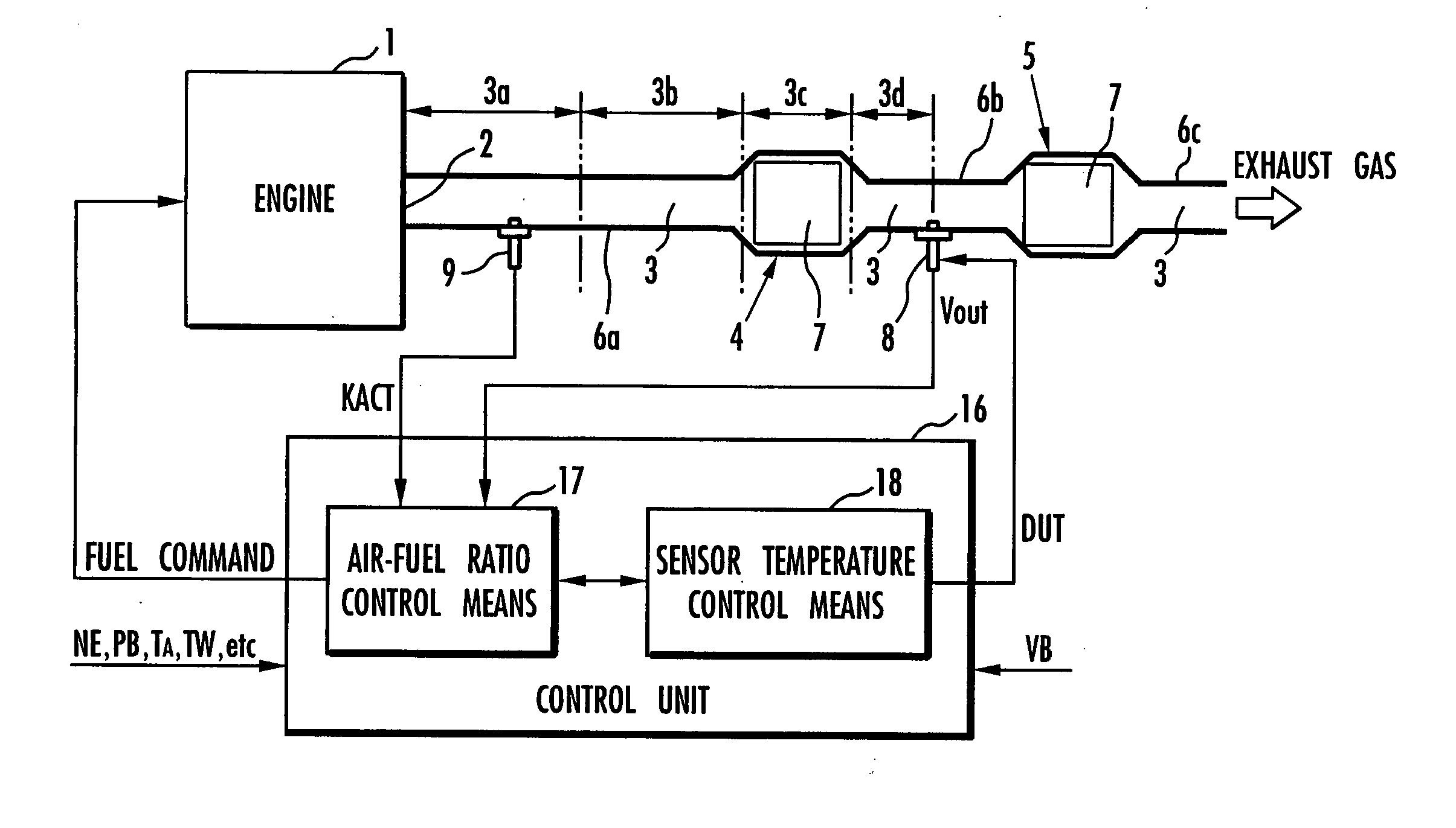
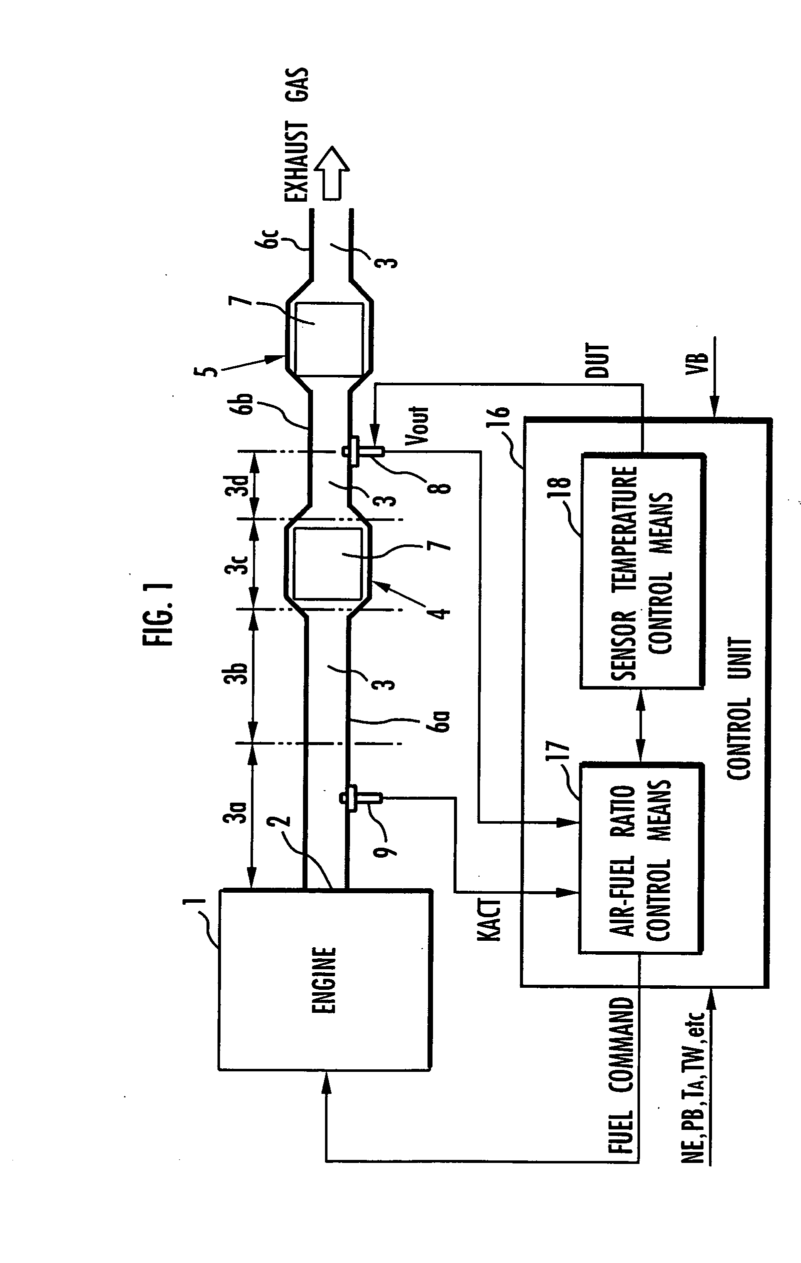
[0114] A first embodiment of the present invention will be described below with reference to FIGS. 1 through 13. FIG. 1 shows in block form an overall arrangement of the apparatus according to the first embodiment of the present invention. In FIG. 1, an engine (an internal combustion engine) 1 mounted on an automobile, a hybrid vehicle, or the like combusts a mixture of fuel and air and generates an exhaust gas, which is discharged into the atmosphere through an exhaust passage 3 communicating with an exhaust port 2 of the engine 1. The exhaust passage 3 incorporates therein two catalytic converters 4, 5 disposed successively downstream for purifying the exhaust gas emitted from the engine 1 and flowing through the exhaust passage 3. The exhaust passage 3 includes a section upstream of the catalytic converter 4 (between the exhaust port 2 and the catalytic converter 4), a section between the catalytic converters 4, 5, and a section downstream of the catalytic converter 5. These sect...


PUM

PropertyMeasurementUnit
temperatureaaaaaaaaaa

Abstract

A control input (DUT) for controlling a heater (13) which heats an active element (10) of an exhaust gas sensor (8) includes at least one of another component depending on the difference between temperature data of the active element (10) and a target temperature, a component depending on the target temperature, and a component depending on the temperature data of the active element (10). The control input is determined by an optimum control algorithm. A component depending on the temperature of an exhaust gas and the component depending on the target temperature are determined based on a predictive control algorithm. The temperature of the active element (10) of the exhaust gas sensor (8) is thus controlled stably at a desired temperature.

Description

TECHNICAL FIELD [0001] The present invention relates to an apparatus for and a method of controlling the temperature of an exhaust gas sensor disposed in the exhaust passage of an internal combustion engine, and a recording medium storing a program for controlling the temperature of such an exhaust gas sensor. BACKGROUND ART [0002] Exhaust gas sensors are often disposed in the exhaust passages of internal combustion engines for detecting a physical quantity as to an exhaust gas component state, such as an exhaust gas component concentration, for the purpose of controlling the operation of the internal combustion engine or monitoring the status of an exhaust gas purifying system. Specifically, the exhaust gas sensor is disposed at a certain location in the exhaust gas passage and has an element sensitive to an exhaust gas component state to be detected, the element being positioned for contact with an exhaust gas flowing through the exhaust passage. For example, an air-fuel ratio sen...

Claims


Application Information

Patent Timeline
Patent Type & Authority Applications(United States)
IPC IPC(8): G01N27/409F02D35/00F02D41/14G01N27/406G05D23/19G05D23/24
CPCG05D23/2401G01N27/4067
Inventor YASUI, YUJIIWAKI, YOSHIHISA
Owner HONDA MOTOR CO LTD
Why Eureka
Try Eureka