Method for improving an optical imaging property of a projection objective of a microlithographic projection exposure apparatus

a technology of exposure apparatus and projection objective, which is applied in the direction of microlithography exposure apparatus, printers, instruments, etc., can solve the problems of difficult temperature change, significantly harder to set a homogeneous temperature distribution throughout the optically active volume, etc., and achieve the effect of improving the optical imaging properties of the projection objective even more easily and effectively

Inactive Publication Date: 2005-12-01
CARL ZEISS SMT GMBH
View PDF8 Cites 52 Cited by
  • Summary
  • Abstract
  • Description
  • Claims
  • Application Information

AI Technical Summary

Benefits of technology

[0009] It is an object of the present invention to provide a method and a microlithographic projection exposure apparatus of the type, in w...

Problems solved by technology

Although in principle it is also possible to change the refractive index of the optical components contained in the projection objective via the temperature, a temperature change is very much more difficult to ...

Method used


Image

  • Method for improving an optical imaging property of a projection objective of a microlithographic projection exposure apparatus
  • Method for improving an optical imaging property of a projection objective of a microlithographic projection exposure apparatus
  • Method for improving an optical imaging property of a projection objective of a microlithographic projection exposure apparatus

Examples


Embodiment Construction

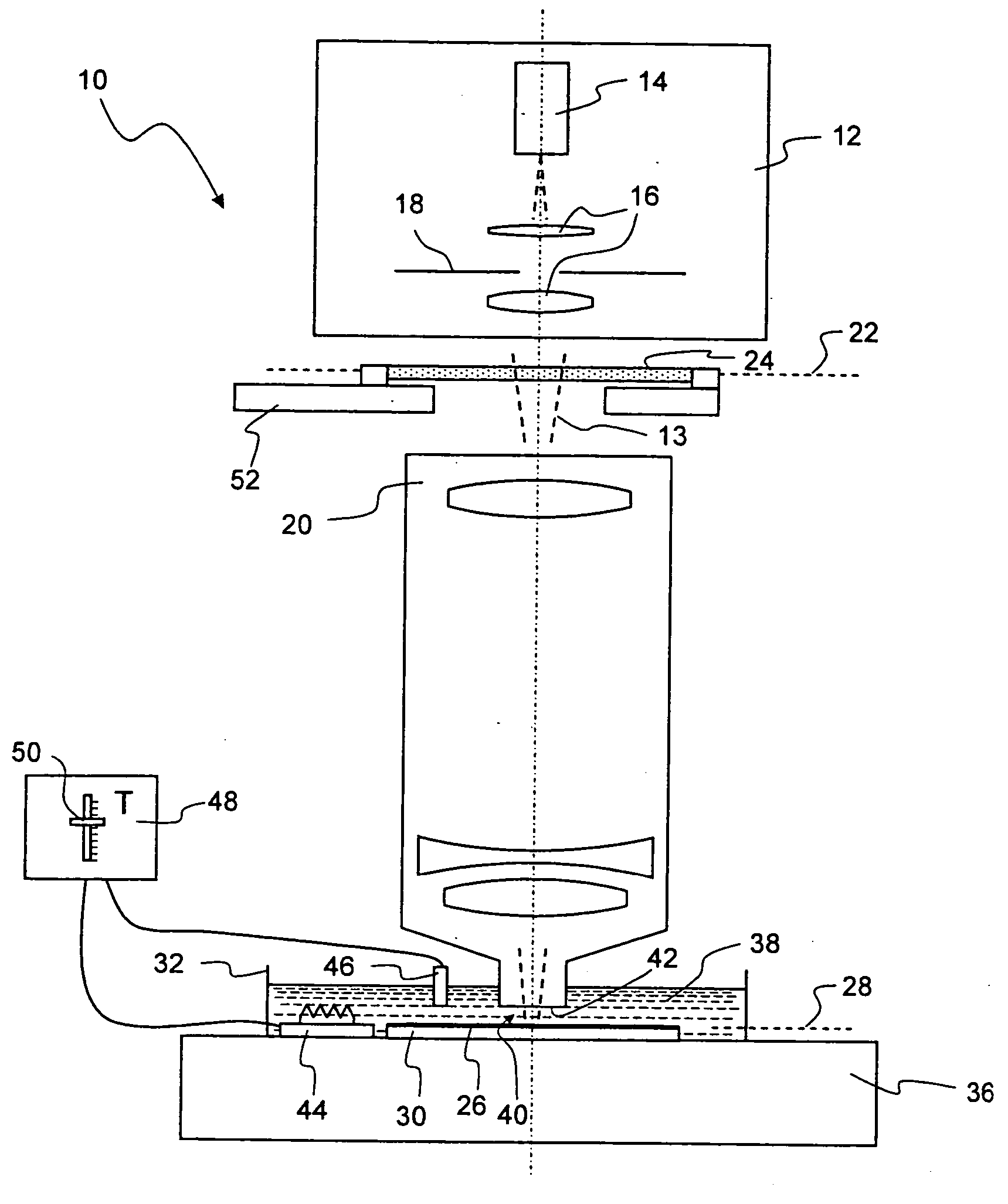
[0032]FIG. 1 shows a microlithographic projection exposure apparatus, denoted in its entirety by 10, in a longitudinal section. The projection exposure apparatus 10 comprises an illumination system 12 for generating a projection light beam 13, which includes a projection light source 14, illumination optics indicated by 16 and a diaphragm 18.

[0033] The projection exposure apparatus 10 furthermore comprises a projection objective 20 which projects a reduced image of a mask 24, arranged in its object plane 22, onto a photosensitive surface 26 arranged in an image plane 28 of the projection objective 20. The projection objective 20 contains a multiplicity of optical components, only some of which (not dealt with in detail) are represented by way of example in FIG. 1.

[0034] The photosensitive surface 26 may, for example, be a photoresist which is applied on a support 30, for example a silicon wafer. The support is fastened on the bottom of an open-topped container 32 with the shape of...


PUM


Abstract

A method is disclosed for improving an optical imaging property, for example spherical aberration or the focal length, of a projection objective of a microlithographic projection exposure apparatus. First, an immersion liquid is introduced into an interspace between a photosensitive surface and an end face of the projection objective. Then an imaging property of the projection objective is determined, for example using an interferometer or a CCD sensor arranged in an image plane of the projection objective. This imaging property is compared with a target imaging property. Finally, the temperature of the immersion liquid is changed until the determined imaging property is as close as possible to the target imaging property.

Description

CROSS-REFERENCE TO RELATED APPLICATIONS [0001] This is a continuation application of international application PCT / EP2003 / 001564, filed Feb. 17, 2003, which claims priority of German patent application DE 102 57 766.8, filed Dec. 10, 2002. The fill disclosure of both earlier applications is incorporated herein by reference.BACKGROUND OF THE INVENTION [0002] 1. Field of the Invention [0003] The invention generally relates to microlithographic projection exposure apparatuses as are used in the manufacture of integrated circuits and other microstructured devices. More particularly, the invention relates to a method for improving an optical imaging property, for example spherical aberration or the focal length, of a projection objective of such an apparatus. The invention further relates to a microlithographic projection exposure apparatus as such. [0004] 2. Description of Related Art [0005] It is known to change the spatial position of individual optical components, for example by usin...

Claims


Application Information

Patent Timeline
IPC IPC(8): G03F7/20
CPCG03F7/70258G03F7/70891G03F7/706G03F7/70341
Inventor GRAEUPNER, PAUL
Owner CARL ZEISS SMT GMBH
Why Eureka
Try Eureka