Optical interrogation systems with reduced parasitic reflections and a method for filtering parasitic reflections

a technology parasitic reflection, which is applied in the field of optical interrogation system, can solve the problems of reducing the quality of the detected resonant signal, reducing the signal to noise ratio, and reducing the accuracy of the angular or wavelength measurement of the resonan

Inactive Publication Date: 2005-12-01
CORNING INC
View PDF21 Cites 51 Cited by
  • Summary
  • Abstract
  • Description
  • Claims
  • Application Information

AI Technical Summary

Benefits of technology

[0023] Yet another advantage of the present invention is that both direction of light propagation and/or both TM and TE modes can be utilized to derive resonant signals from the sensor.
[0024] Additional features and advantageous of the present invention will be revealed in the following detailed description. Both the foregoing summary and the following detailed description and examples are merely representative of the invention, and are intended to provide an overview for understanding the invention as claimed. Reference to the accompanying figures and the following detailed description may co...

Problems solved by technology

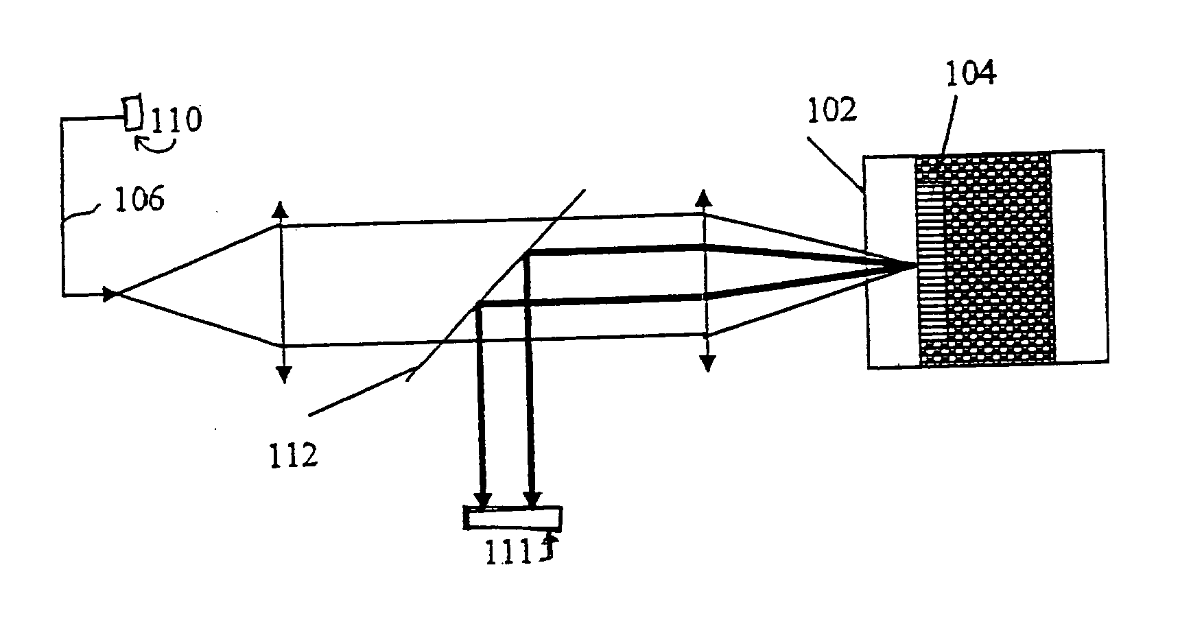
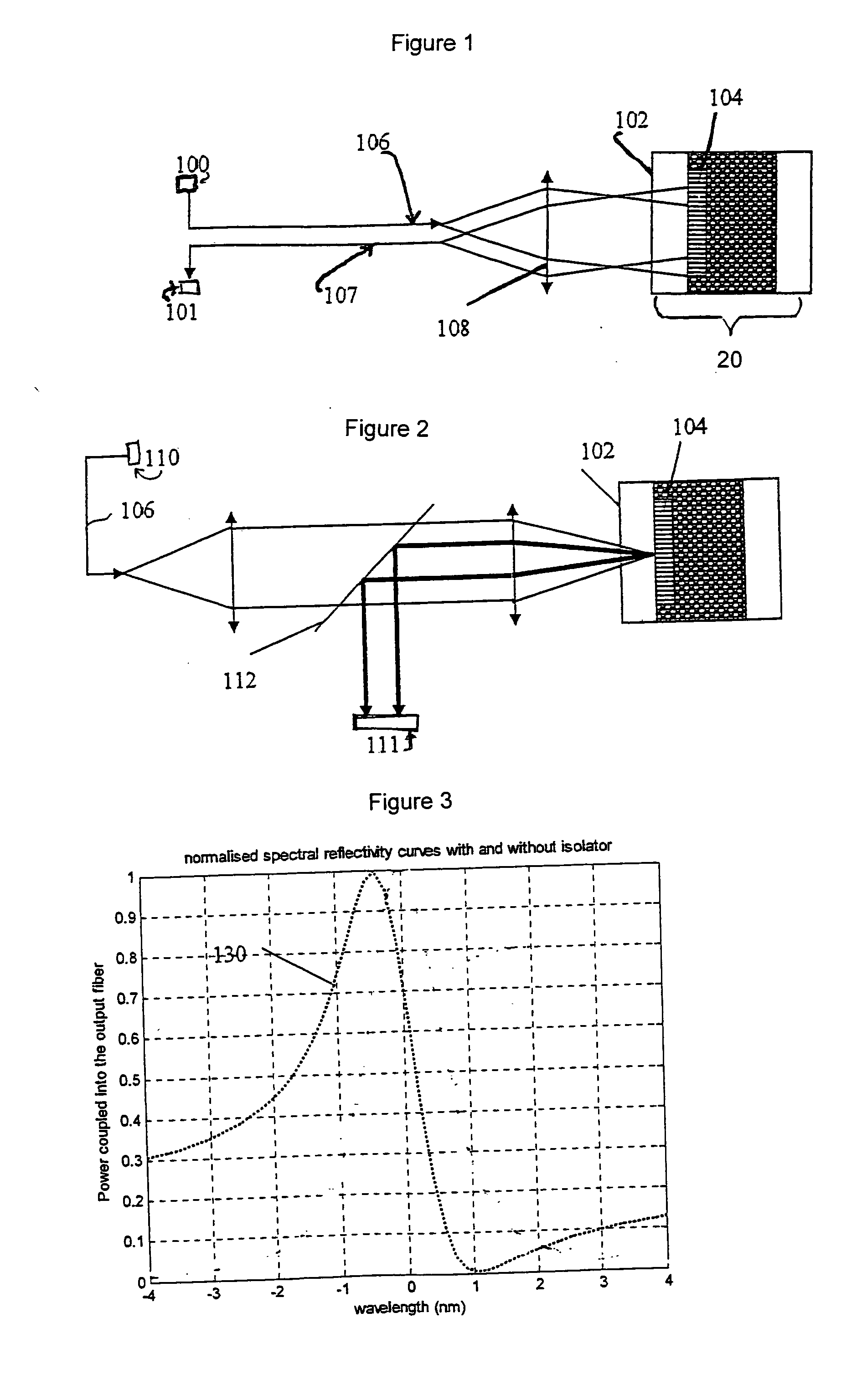
However, in addition to reflecting light at the resonance wavelength or the resonance angle, grating-coupled waveguides (GCWs) also reflect light at other wavelengths and angles (parasitic geometric reflections), thus reducing the quality of the detected resonant signal.
The background lowers signal to noise ratio and makes the angular or wavelength measurement of the resonance less accurate.
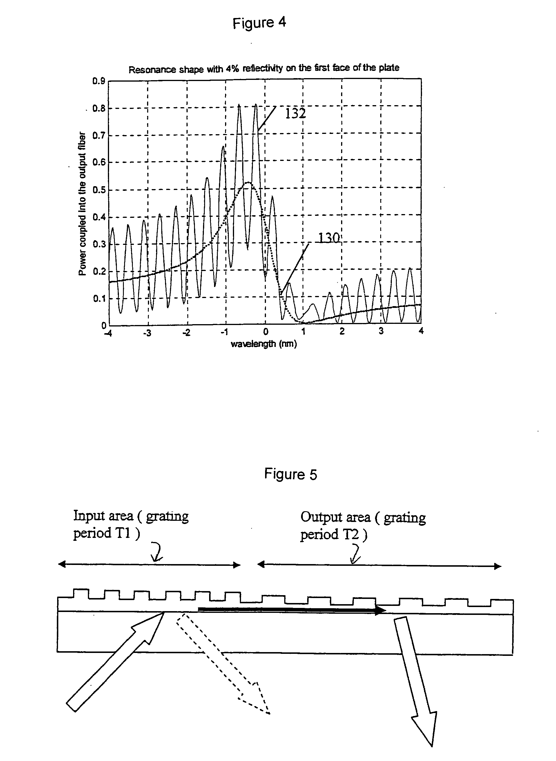
A second problem is caused by the reflections from the first (front) surface of the substrate or microplate, which are referred to herein as parasitic Fresnel reflections.
Parasitic Fresnel reflections interfere with the resonance measurements and generate fringes in the angular or spectral space making the resonance detection very noisy and, due to temperature fluctuations and other factors, instable over time.
However, as stated above, both of these approaches suffer from parasitic reflections which obscure the true resonance signal.
The solution described by Cottier, K., et al., however, is limited to unidirectional light propagation.
Therefore, Cottier's solution is not compatible with a double resonance ...

Method used


Image

  • Optical interrogation systems with reduced parasitic reflections and a method for filtering parasitic reflections
  • Optical interrogation systems with reduced parasitic reflections and a method for filtering parasitic reflections
  • Optical interrogation systems with reduced parasitic reflections and a method for filtering parasitic reflections

Examples


example 1

[0059] The above described embodiments of the present invention (shown in FIGS. 7 and 10) utilize an optical isolator 105. The optical isolator 105 filters parasitic reflections without requiring any spatial or angular separation between the input beam (incident on the GCW) and the collected output beam (reflected by the GCW). More specifically, FIGS. 7 and 10 show one exemplary implementation of the isolator 105 into a wavelength sensing optical interrogation system (FIG. 7), or into the optical interrogation system that utilizes an angular interrogation (FIG. 8). In these two embodiments of the optical interrogation systems the optical isolator 105 is a polarization sensitive isolator.

[0060] An example of the polarization sensitive isolator 105 is shown schematically in FIG. 11. According to this embodiment, this isolator includes a linear polarizer 120 and quarter waveplate 121. The linear polarizer 120 has its polarization axis 122 oriented at 45 degrees relative to the polariz...

example 2

[0062] Another example of the isolator 105 is shown schematically in FIG. 12. The isolator 105 of this example includes a polarizer 120 and a Faraday rotator 125. As the incoming light beam (propagating toward the GCW) passes through the polarizer 120 it becomes linearly polarized. After the light beam passes trough the Faraday rotator 125 its polarization is still linear, but the polarization vector 126 of the propagating light is rotated by 45 degrees. After the reflection, the polarization orientation (polarization vector) for the light associated with all parasitic reflections is not changed until this light propagates again trough the Faraday rotator, which again rotates the light's polarization axis by 45 degrees. Since the polarization axis of this light is now rotated by 90 degrees with respect to the axis 122 of the polarizer 120, parasitic reflections are filtered by the polarizer 120.

[0063] If the grating of the GCW 104 is oriented either along or perpendicular to the di...

example 3

[0065] This exemplary optical isolator (FIG. 14) is similar to the optical isolator of Example 1. However, the polarizer 120 of the isolator 105 is made of a birefringent beam displacing polarizing material, for example, YVO4, quartz or any other material presenting a large birefringence Δn, to separate the incoming beam into two differently (linearly) polarized input beam components. Having two input light beams instead of one light beams allows us to simultaneously interrogate at least two GCWs 104. This is illustrated schematically in FIG. 14. FIG. 14 shows that the non polarized beam input A′ is separated, by the polarizer 120, into two beams B1 and B2. The input light beams B1 and B2 have linear polarizations that are perpendicular to one another, which become circularly polarized after crossing the waveplate 121. The two GCWs 104 have slightly different effective refractive indices (for example, due to slightly different thicknesses), so that they couple in and then reflect li...


PUM


Abstract

The optical interrogation system comprises an optical sensor and an optical isolator that filters parasitic reflections introduced by the optical sensor.

Description

FIELD OF INVENTION [0001] The present invention pertains in general to optical interrogation systems that utilize optical sensors for label-independent detection of biological and chemical agents. More particularly, the invention relates to 1) a method for filtering parasitic reflections generated in a sensor that reflects polarized optical beam, and 2) an optical interrogation system capable of filtering parasitic reflections. BACKGROUND [0002] Optical interrogation systems that utilize evanescent field-based sensors are fast becoming a technology of choice for accurate label-free detection of a biological, biochemical, or chemical substance (e.g., cells, spores, biological or drug molecules, or chemical compounds). This technology typically involves the use of grating-coupled waveguides (GCWs) to sense a concentration change, surface adsorption, reaction, or the mere presence of a biological or chemical substance at the waveguide surface. Evanescent field-based sensors typically u...

Claims


Application Information

Patent Timeline
IPC IPC(8): G01N21/77
CPCG01N2021/7776G01N21/7743
Inventor GOLLIER, JACQUES
Owner CORNING INC
Why Eureka
Try Eureka