
Method of providing consistent quality of target material removal by lasers having different output performance characteristics

a laser and output performance technology, applied in the field of providing consistent quality of target material removal by lasers having different output performance characteristics, can solve the problems of short-term transients, differences in drilled via quality, and imperfect control of pulse energy

Inactive Publication Date: 2005-12-01
ELECTRO SCI IND INC
View PDF8 Cites 22 Cited by
  • Summary
  • Abstract
  • Description
  • Claims
  • Application Information

AI Technical Summary

Benefits of technology

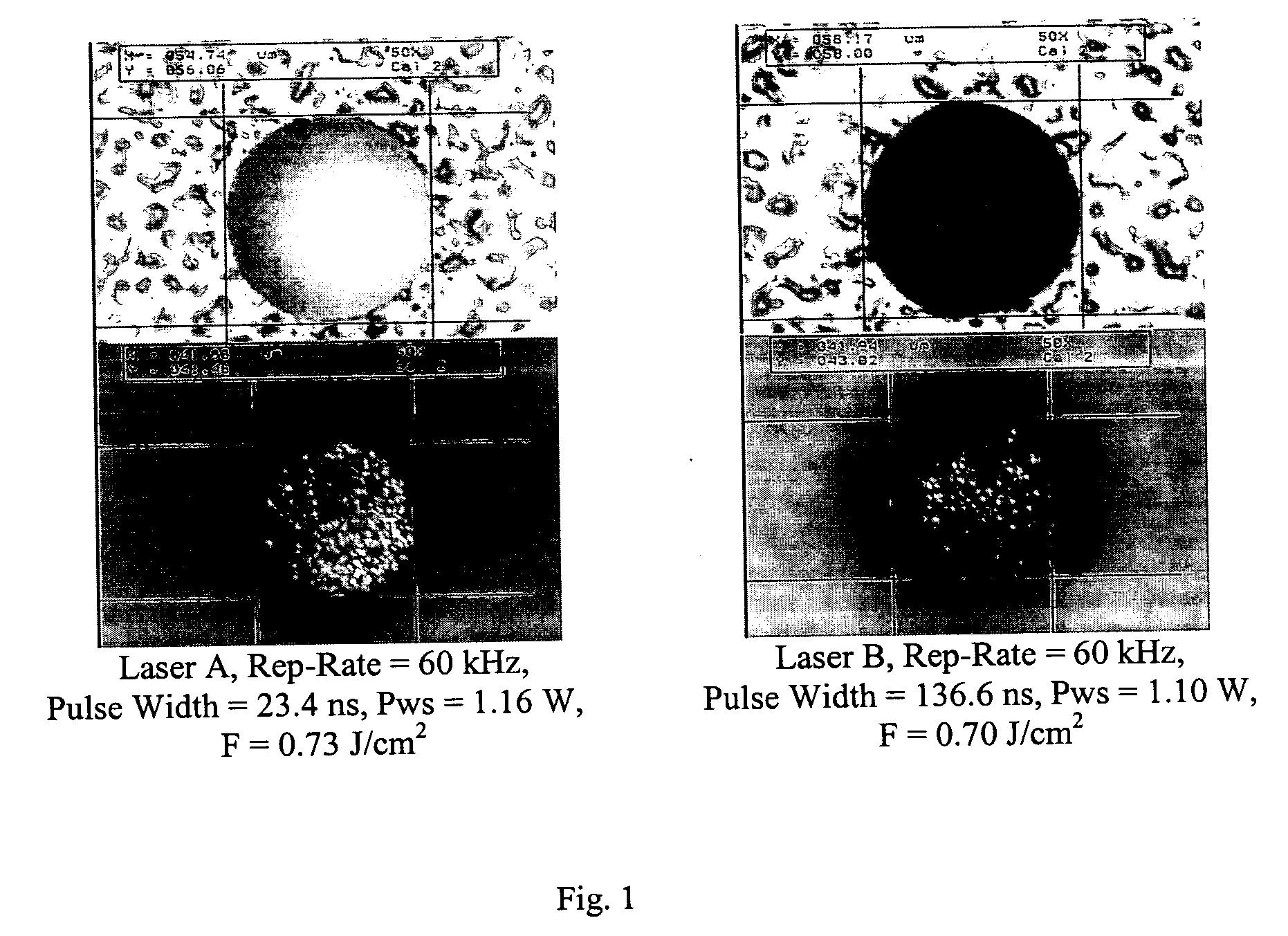
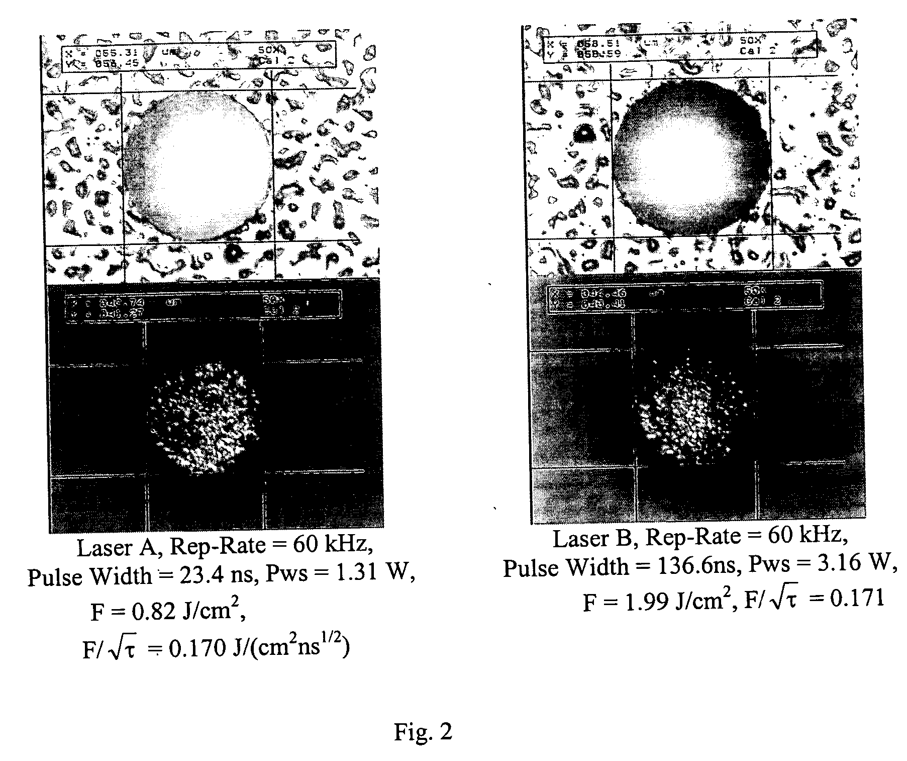
[0010] The conventional method-of controlling a via drilling process entails controlling the pulse energy for the given process. The pulse energy, Ep, for use in performing a given process is determined by the fluehce, F, desired for the process. The fluence, in J / cm2, is calculated as F=EPπ4⁢D2, where Ep is the pulse energy in J and D is the via diameter in cm. Applicants have found that drilling the same material at the same fluence level with lasers having different pulse widths results in different quality for the bottom copper cladding layer of a target specimen. Applicants have determined that a more appropriate parameter for predicting the bottom copper cladding quality for blind vias is F / {square root}{square root over (τ)}, where F is the pulse fluence in J / cm2 and τ is the laser pulse width in ns. Taking steps to keep F / {square root}{square root over (τ)} constant among lasers in a group of different lasers provides more consistent laser processing. This is true for laser processing operations other than via drilling and targets other than those having copper cladding.

Problems solved by technology

Variation in laser output performance characteristics within the specified limits can result in differences in drilled via quality among multiple lasers, multiple beam positioning heads, and multiple laser systems, even when the same process is performed and same material is used on all systems.
Specifically, variation in parameters within the specifications of the laser can cause, especially for blind via drilling applications, bottom copper cladding residue formation or nonhomogeneous melting, which results in differences in drilled via quality.
Moreover, the control of pulse energy is imperfect and is subject to short-term transients that may not be normalized by energy control devices present in the optical system.
Such deviations in pulse energy can cause undesirable variations in via quality metrics.

Method used


Image

  • Method of providing consistent quality of target material removal by lasers having different output performance characteristics
  • Method of providing consistent quality of target material removal by lasers having different output performance characteristics
  • Method of providing consistent quality of target material removal by lasers having different output performance characteristics

Examples


Embodiment Construction

[0016] Preferred embodiments of this invention entail the use of a solid state UV laser to perform via drilling and ablation of electronic circuit materials such as homogenous films, particulate filled resins, polyimides, and fiber-reinforced polymers, either with or without metal cladding. The Model ABF circuit board dielectric material manufactured by Ajinomoto Fine-Techno Co., Inc., Kawasaki, Japan is the target material on which the following descriptions are based. The following descriptions are directed to via drilling, but the invention is also applicable to other methods of material removal, such as link severing, material trimming, annealing, and scribing.

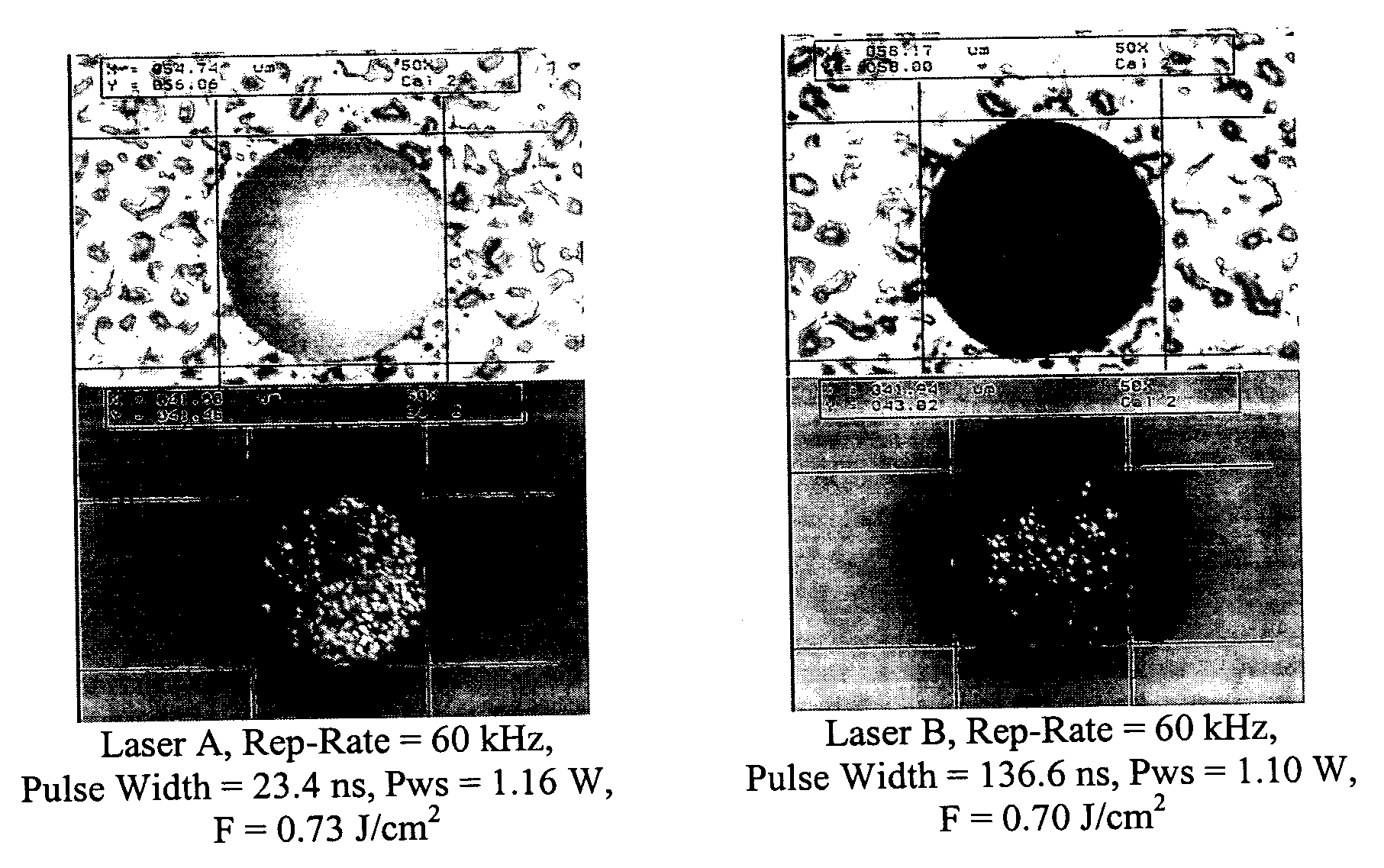
[0017]FIG. 1 is a set of four photographs of microscope images that illustrate the problem solved by the invention. FIG. 1 shows light microscope pictures of two 58 μm diameter vias drilled to depths of 35 μm-40μm at approximately the same fluence level with 355 nm UV lasers having different pulse widths. The top two phot...


PUM

PropertyMeasurementUnit
Widthaaaaaaaaaa
Energyaaaaaaaaaa
Pulsed soundaaaaaaaaaa

Abstract

Laser pulse energy adjustments are motivated by an understanding of the effect of laser pulse width variations among different lasers on satisfying a quality metric associated with a laser-processed target. In a preferred embodiment, the adjustments normalize this effect among different lasers drilling vias in a target specimen. The number of pulses delivered to the target specimen to form each via can be modified, based on the pulse energy applied to the via location, to control different via quality metrics.

Description

RELATED APPLICATION [0001] This application claims benefit of U.S. Provisional Patent Application No. 60 / 575,228, filed May 28, 2004.COPYRIGHT NOTICE [0002]© 2005 Electro Scientific Industries, Inc. A portion of the disclosure of this patent document contains material that is subject to copyright protection. The copyright owner has no objection to the facsimile reproduction by anyone of the patent document or the patent disclosure, as it appears in the Patent and Trademark Office patent file or records, but otherwise reserves all copyright rights whatsoever. 37 CFR § 1.71 (d). TECHNICAL FIELD [0003] This invention relates to use of a laser to drill vias in or otherwise process portions of material of electronic materials products and, in particular, to techniques of achieving with consistent high quality vias drilled or regions formed after material processing by laser-based systems exhibiting different operating output parameters. BACKGROUND INFORMATION [0004] Lasers are used to dr...

Claims


Application Information

Patent Timeline
IPC IPC(8): B23K26/06B23K26/38H01S3/10H05K3/00
CPCB23K26/063B23K26/381B23K2201/36H05K3/0032B23K26/4095B23K26/401B23K26/4065B23K26/4085H05K2203/163B23K26/0622B23K26/382B23K26/40B23K2101/34B23K2101/35B23K2101/36B23K2103/16B23K2103/42B23K2103/50H01S3/10
Inventor LEI, WEISHENGSIMENSON, GLENNHOWERTON, JEFFUNRATH, MARK
Owner ELECTRO SCI IND INC
Learn More