Long-stroke, high-resolution nanopositioning mechanism

a nanopositioning mechanism and long stroke technology, applied in the field of nanopositioning devices and fixed seats, can solve the problems of nanomaterial properties such as optical properties, magnetic properties, diffusion properties and machinery properties, and cannot provide nanometer scale displacements within a long stroke range. the manufacturing cost of the nanopositioning device of the present invention can be much lower, and the structure is simple and less complex.

Inactive Publication Date: 2005-12-08
IND TECH RES INST
View PDF2 Cites 15 Cited by
  • Summary
  • Abstract
  • Description
  • Claims
  • Application Information

AI Technical Summary

Benefits of technology

[0008] It is an object of the present invention to provide a long-stroke nanopositioning device so as to actuate nanometer scaled displacements in one-dimensional, two-dimensional nanometer and three-dimensional. It not only overcomes the drawbacks of the commercial nanopositioning mechanisms of the present time, but also provides a long stroke, nanometer scaled displacement of a minute probe tip. Besides, due to its simple and less-complex structure, the manufacturing cost of the nanopositioning device of the present invention can be much lower than the commercial nanopositioning mechanisms of the present time.
[0009] Another object of the present invention is to provide a fixed seat for a long-stroke nanopositioning device so as to actuate nanometer scaled displacements. It overcomes the drawbacks of the commercial nanopositioning mechanisms of the present time. Besides, due to the adjustable force, the resolution of the nanometer-scaled displacements can be easily adjusted.
[0014] When the long-stroke nanopositioning device is used for a horizontally driving system, the movable plate is supported by a base plate having a plurality of V-shaped quartz guided grooves as to reduce friction in movement and by this way to achieve the nanometer scaled displacements of the movable plate. The long-stroke nanopositioning device of the present invention may be combined with any other nanopositioning devices of the present time to have bi-axial or tri-axial movements, such as the movements in the X-Y-Z coordinate systems or even in the arcuate coordinate systems.

Problems solved by technology

Secondly, the various properties of the nanomaterials such as optical properties, magnetic properties, heat-transfer properties, diffusion properties and machinery properties are different from those of the corresponding bulk material.
Thirdly, metals or polymers that cannot be blended in their bulk phase can now be blended to form an alloy in their nanostructure phase.
However, the nanometer scaled displacements of the moving plates for these microscopes are all limited, and the cost the moving plates are extremely expensive.
However, due to the problems such as the over-sized modules and the nanometer scaled displacements can only be achieved by alternatively tuning the microscopes, the commercial nanopositioning systems of the present time cannot providing the nanometer scaled displacements within a long stroke range.

Method used


Image

  • Long-stroke, high-resolution nanopositioning mechanism
  • Long-stroke, high-resolution nanopositioning mechanism
  • Long-stroke, high-resolution nanopositioning mechanism

Examples


embodiment one

Three-dimensional Long-stroke Nanopositioning Device

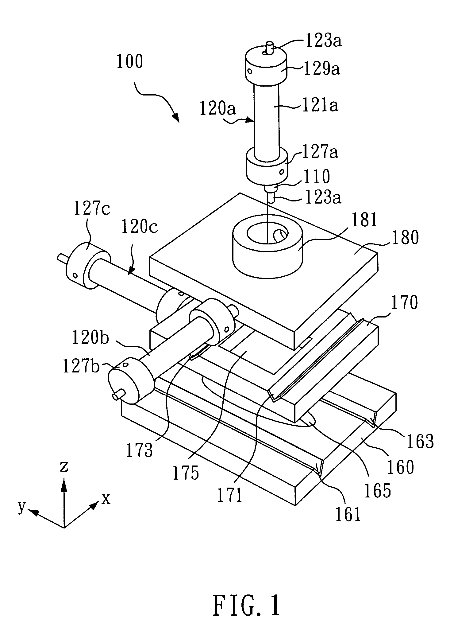
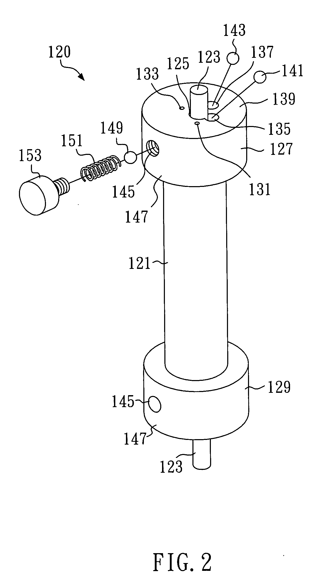
[0021] In this embodiment, a long-stroke nanopositioning device 100 is shown in FIG. 1, which can overcome the drawbacks of the present nanopositioning mechanisms such as movements within a small range. A STM probe tip 110 is positioned on the quartz glass rod 123a of the long-stroke nanopositioning device 100 with long stroke, nanometer scaled displacements. The long-stroke nanopositioning device 100 has three nanopositioning units 120b, 120c and 120a in the X-axis, Y-axis and Z-axis directions respectively. A nanopositioning unit 120 as shown in FIG. 2 comprises a cylindrical PZT tube 121, two ceramic fixed seats 127 and 129 and a wire (not shown). The cylindrical PZT tube 121 has a central hole 125 that is penetrated by a quartz glass rod 123. The ceramic fixed seats 127 and 129 are fixed to the two ends of the cylindrical PZT tube 121 respectively. The wire connects the cylindrical PZT tube 121 with the external PZT actuator ...

embodiment two

Two-dimensional Long-stroke Nanopositioning Device

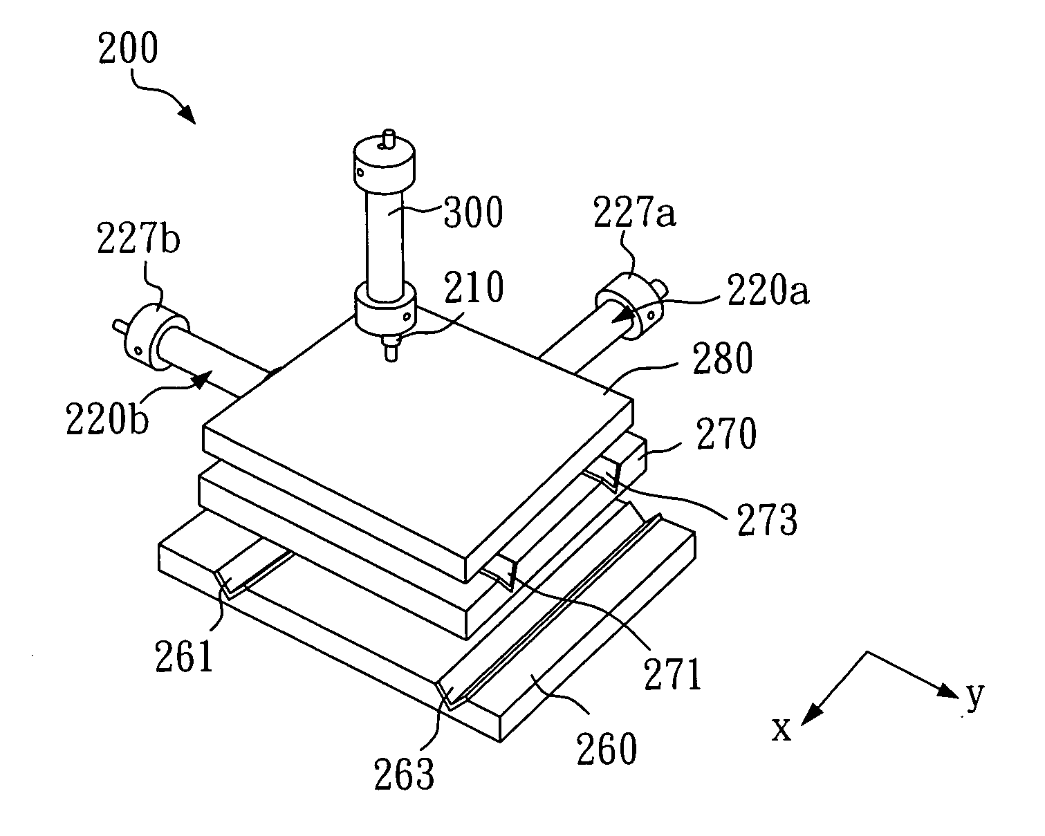
[0026] As shown in FIG. 3, the long-stroke nanopositioning device 200 of this embodiment comprises: the movable plate 280 that is capable of two-dimensional long-stroke nanometer scaled displacements and the nanopositioning unit 300 that is equipped with the STM probe tip 210. The nanopositioning unit 300 can be any conventional nanopositioning mechanism, such as a voltage-controlled piezoelectric element, a thermal-controlled piezoelectric element or a nanopositioning mechanism utilizing laser light path. The long-stroke nanopositioning device 200 has two nanopositioning units 220a and 220b in the X-axis and Y-axis directions, respectively. Each of these nanopositioning units has the same structures as those of the one shown in FIG. 2.

[0027] The long-stroke nanopositioning device 200 comprises: a base 260 and a movable plate 270. The base has V-shaped quartz glass guided grooves 261 and 263 along the X direction and the movable p...

embodiment three

Rotating Long-stroke Nanopositioning Device

[0029] As shown in FIG. 4, the long-stroke nanopositioning device 400 can overcome the drawbacks of the present nanopositioning mechanisms such as movements within a small range. A probe tip 411 is positioned on the supporting seat 410 which is disposed in a ceramic fixed seat 427 of the long-stroke nanopositioning device 400 with long stroke, nanometer scaled displacements. A nanopositioning unit 420 is assembled to a fixed quartz glass rod 423. The supporting seat 410 can be rotated around the shaft 430. The nanopositioning unit 420 of the embodiment is the same as that of aforesaid embodiment that is shown in FIG. 2. Thereofore, it will not be described again herein.

[0030] While the long-stroke nanopositioning device 400 of this embodiment is in operation, the quartz glass rod 423 is fixed in position. The nanopositioning unit 420 has relative displacements on the quartz glass rod 423 by the driving force from the deformation the PZT ...


PUM


Abstract

The present invention relates to a long-stroke nanopositioning device, comprising: a piezoelectric tube; a quartz glass rod; two fixed seats being disposed on the ends of the piezoelectric tube and a piezoelectric actuator. Each of the fixed seats has a base for receiving at least one spring and a plurality of ruby balls. The quartz glass rod is gripped to the fixed seat by the ruby balls of the fixed seat wherein the gripping force is controlled by means of the spring. The piezoelectric actuator applies an input voltage to the piezoelectric tube to cause one end of the piezoelectric tube to have a relative displacement in a direction along the axis of the quartz glass rod. The present invention provides a nanopositioning device capable of long stroke displacements at the nanometer scale by controlling the input voltage of the piezoelectric actuator and the gripping force of the ruby balls.

Description

BACKGROUND OF THE INVENTION [0001] 1. Field of the Invention [0002] The present invention relates to a nanopositioning device and a fixed seat made of piezoelectric material thereof, and more particularly, to a long-stroke nanopositioning device and a fixed seat made of piezoelectric material thereof. [0003] 2. Description of Related Art [0004] Due to the various properties of the nanostructured materials all vary with the materials' grain sizes, the various unique properties of the nanostructured materials have gradually attracted technicians' attention in the field. The main characteristics of the nanomaterials with nanostructures are as follow: Firstly, the nanostructure of a nanomaterial formed in either crystalline phase or amorphous phase is much different from that of the corresponding bulk material. Secondly, the various properties of the nanomaterials such as optical properties, magnetic properties, heat-transfer properties, diffusion properties and machinery properties are...

Claims


Application Information

Patent Timeline
Patent Type & Authority Applications(United States)
IPC IPC(8): B81B3/00G01Q10/00G01Q10/04H01L41/04H01L41/053H01L41/09H02N2/00
CPCB82Y35/00H02N2/028G01Q10/04
Inventor PAN, SHAN-PENGCHANG, WEI-CHENGYAO, BIN-CHENG
Owner IND TECH RES INST
Why Eureka
Try Eureka