Long-stroke, high-resolution nanopositioning mechanism
a nanopositioning mechanism and long stroke technology, applied in the field of nanopositioning devices and fixed seats, can solve the problems of nanomaterial properties such as optical properties, magnetic properties, diffusion properties and machinery properties, and cannot provide nanometer scale displacements within a long stroke range. the manufacturing cost of the nanopositioning device of the present invention can be much lower, and the structure is simple and less complex.
- Summary
- Abstract
- Description
- Claims
- Application Information
AI Technical Summary
Benefits of technology
Problems solved by technology
Method used
Image
Examples
embodiment one
Three-dimensional Long-stroke Nanopositioning Device
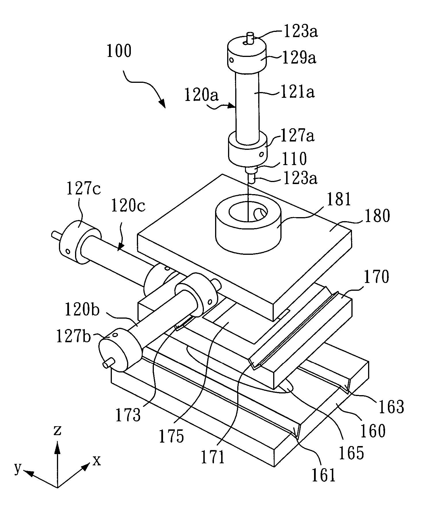
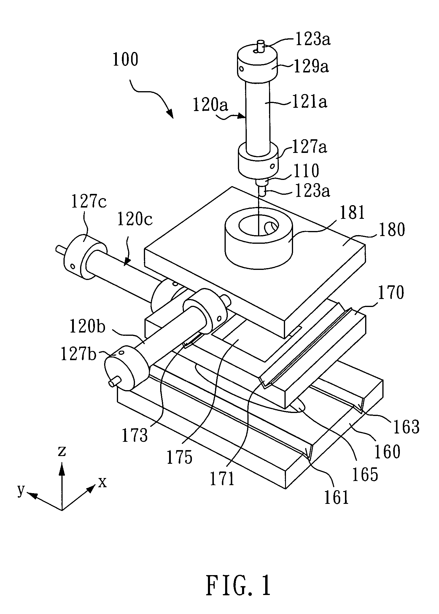
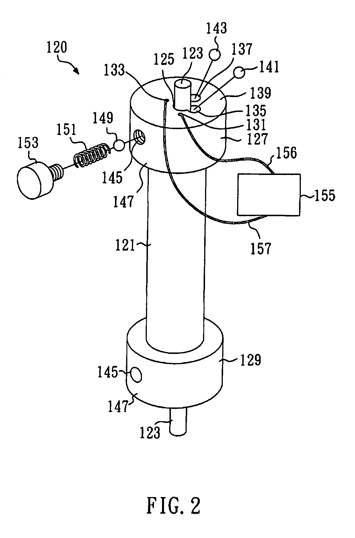
[0021]In this embodiment, a long-stroke nanopositioning device 100 is shown in FIG. 1, which can overcome the drawbacks of the present nanopositioning mechanisms such as movements within a small range. A STM probe tip 110 is positioned on the quartz glass rod 123a of the long-stroke nanopositioning device 100 with long stroke, nanometer scaled displacements. The long-stroke nanopositioning device 100 has three nanopositioning units 120b, 120c and 120a in the X-axis, Y-axis and Z-axis directions respectively. A nanopositioning unit 120 as shown in FIG. 2 comprises a cylindrical PZT tube 121, two ceramic fixed seats 127 and 129 and wires 156 and 157. The cylindrical PZT tube 121 has a central hole 125 that is penetrated by a quartz glass rod 123. The ceramic fixed seats 127 and 129 are fixed to the two ends of the cylindrical PZT tube 121 respectively. The wires 156 and 157 connect the cylindrical PZT tube 121 with the external PZT a...
embodiment two
Two-dimensional Long-stroke Nanopositioning Device
[0026]As shown in FIG. 3, the long-stroke nanopositioning device 200 of this embodiment comprises: the movable plate 280 that is capable of two-dimensional long-stroke nanometer scaled displacements and the nanopositioning unit 300 that is equipped with the STM probe tip 210. The nanopositioning unit 300 can be any conventional nanopositioning mechanism, such as a voltage-controlled piezoelectric element, a thermal-controlled piezoelectric element or a nanopositioning mechanism utilizing laser light path. The long-stroke nanopositioning device 200 has two nanopositioning units 220a and 220b in the X-axis and Y-axis directions, respectively. Each of these nanopositioning units has the same structures as those of the one shown in FIG. 2.
[0027]The long-stroke nanopositioning device 200 comprises: a base 260 and a movable plate 270. The base has V-shaped quartz glass guided grooves 261 and 263 along the X direction and the movable plate ...
embodiment three
Rotating Long-stroke Nanopositioning Device
[0029]As shown in FIG. 4, the long-stroke nanopositioning device 400 can overcome the drawbacks of the present nanopositioning mechanisms such as movements within a small range. A probe tip 411 is positioned on the supporting seat 410 which is disposed in a ceramic fixed seat 427 of the long-stroke nanopositioning device 400 with long stroke, nanometer scaled displacements. A nanopositioning unit 420 is assembled to a fixed quartz glass rod 423. The supporting seat 410 can be rotated around the shaft 430. The nanopositioning unit 420 of the embodiment is the same as that of aforesaid embodiment that is shown in FIG. 2. Thereofore, it will not be described again herein.
[0030]While the long-stroke nanopositioning device 400 of this embodiment is in operation, the quartz glass rod 423 is fixed in position. The nanopositioning unit 420 has relative displacements on the quartz glass rod 423 by the driving force from the deformation the PZT tube ...
PUM
 Abstract
Description
Claims
Application Information
 - R&D
- Intellectual Property
- Life Sciences
- Materials
- Tech Scout
- Unparalleled Data Quality
- Higher Quality Content
- 60% Fewer Hallucinations
Browse by: Latest US Patents, China's latest patents, Technical Efficacy Thesaurus, Application Domain, Technology Topic, Popular Technical Reports.
© 2025 PatSnap. All rights reserved.Legal|Privacy policy|Modern Slavery Act Transparency Statement|Sitemap|About US| Contact US: help@patsnap.com


