Composition for opaque coating, lamp with coating, and method of manufacture

a technology of opaque coating and lamp, applied in the direction of instruments, discharge tube luminescnet screens, lighting and heating apparatus, etc., can solve the problems uneven surface of opaque coating, etc., and achieve the effect of low refraction coefficient and simple method of coating manufacturing

Inactive Publication Date: 2005-12-08
GENERAL ELECTRIC CO
View PDF2 Cites 0 Cited by
  • Summary
  • Abstract
  • Description
  • Claims
  • Application Information

AI Technical Summary

Benefits of technology

[0008] The disclosed composition, when burned, provides an opaque coating on the glass which has a silvery appearance close to that of pure aluminum. The coating is very stable and tolerates temperatures up to 550° C. without any significant degradation of the mechanical or optical properties. This is also due to the fact that the coating contains exclusively inorganic components. Surprisingly, even when the known iron powder based coatings do appear mat and black, the coating made of the suggested composition appears to the human eye as having very pleasant silvery look, and even appear to be glossy to some extent. However, this silvery surface is quite mat (dull), and it is actually a diffuse surface that has a relatively low refraction coefficient. This means that substantially no light is reflected back towards the base of the lamp, and therefore no parasitic light effects will disturb the light beam projected from an automotive reflector where the lamp itself is mounted.
[0009] At the same time, the method to manufacture the coating is very simple, concerning both the components of the composition and the manufacturing steps employed. The application of the coating to the lamps, and their finishing treatment may be performed with standard, or at least very similarly constructed or only slightly modified lamp manufacturing equipment.

Problems solved by technology

However, this silvery surface is quite mat (dull), and it is actually a diffuse surface that has a relatively low refraction coefficient.

Method used


Image

  • Composition for opaque coating, lamp with coating, and method of manufacture
  • Composition for opaque coating, lamp with coating, and method of manufacture
  • Composition for opaque coating, lamp with coating, and method of manufacture

Examples


example

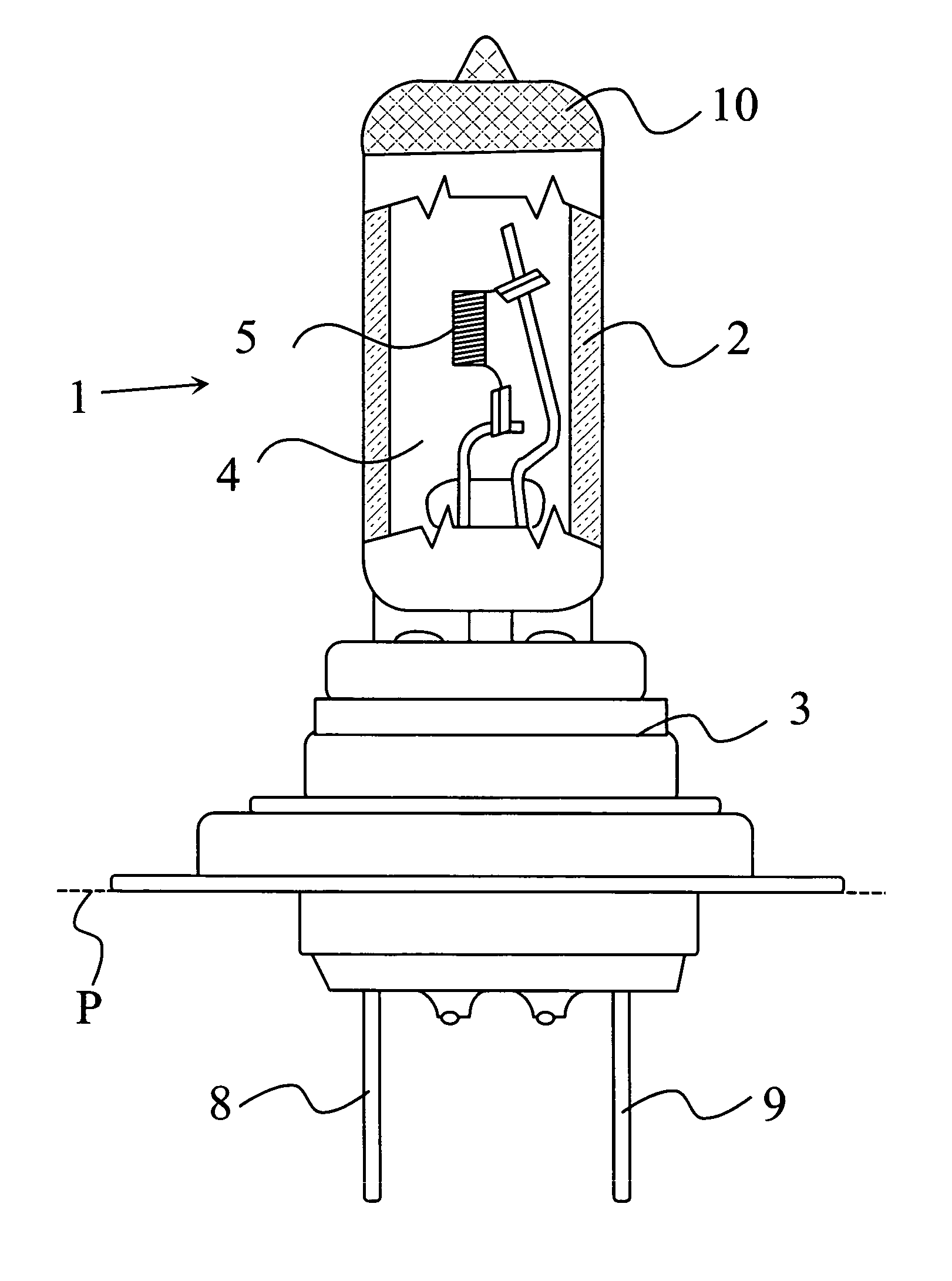
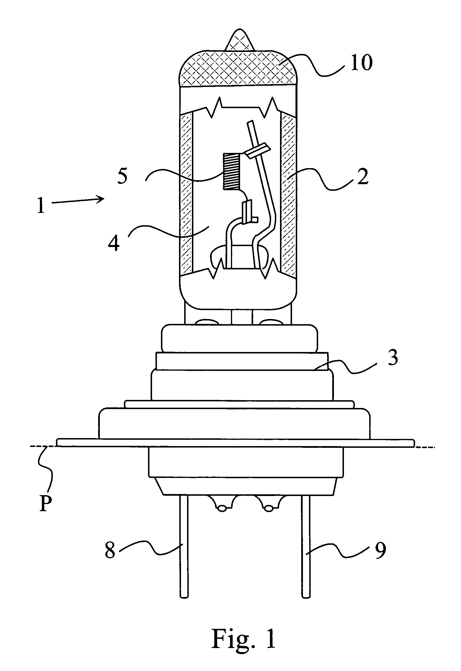
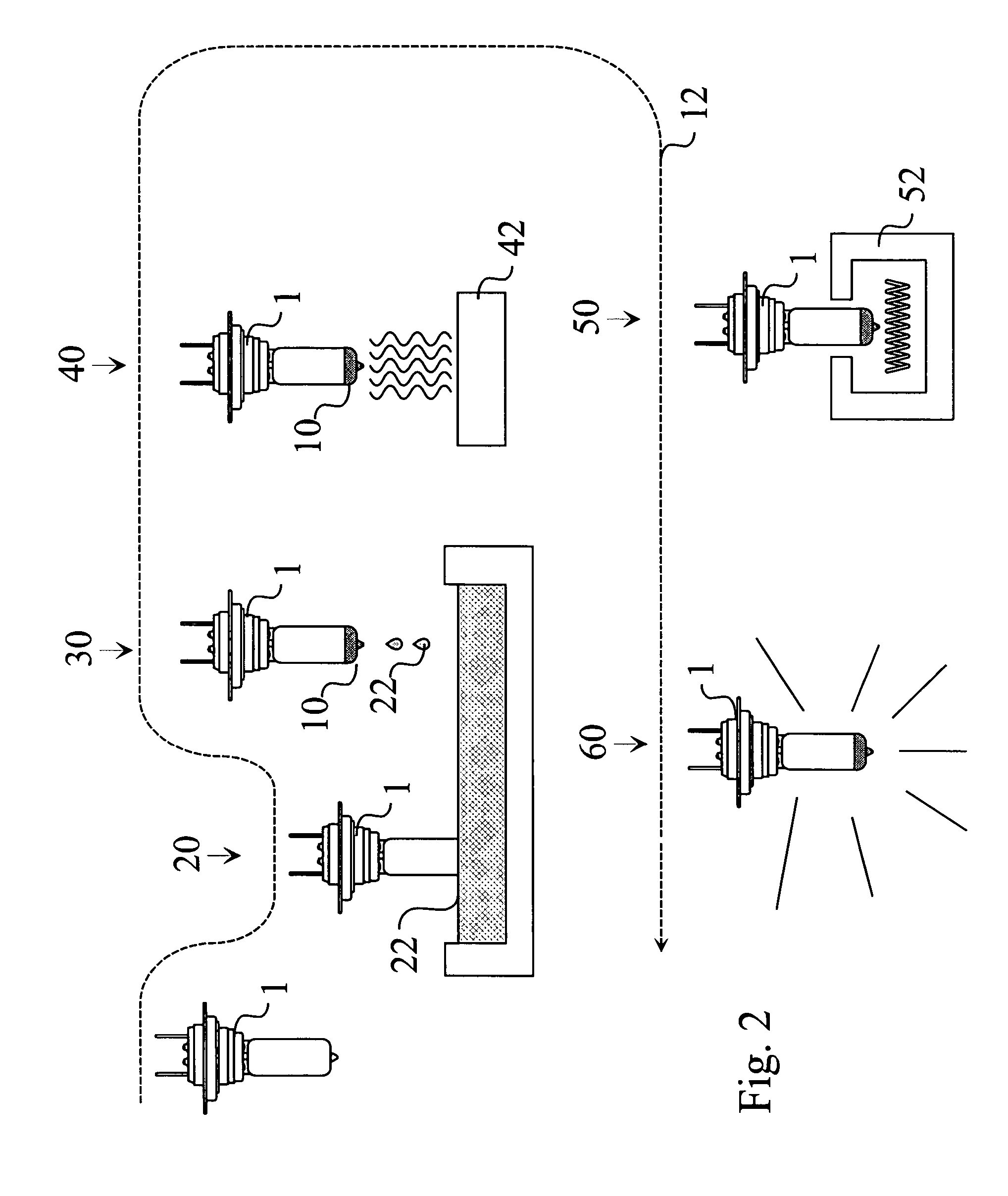
[0025] A suspension containing 100 parts of aluminum, 170 parts of carbonyl iron, and 200 parts of n-butanol was prepared. The n-butanol and the iron were milled in a ball mill for 48 hours. The aluminum was added and the mixture was milled for another 2 hours. Thereafter the suspension was applied to a H4 automotive lamp by dipping it into the suspension, and dried with forced hot air at a temperature of 260° C. for 30 seconds. Burning the Fe—Al mixture for 100 seconds followed the drying. The burning was effected at continuously rising temperature, starting from 260° C. and ending at 640° C.

[0026] The finished lamps were subjected to aging tests by operating the lamps at increased voltage (14 V) for as long as 300 hours. The opaque silvery layer did not show any significant change or deterioration. The layer remained mechanically stable, did not flake off the glass, and also maintained its silvery appearance.

[0027] The invention is not limited to the shown and disclosed embodime...


PUM

PropertyMeasurementUnit
thicknessaaaaaaaaaa
temperatureaaaaaaaaaa
temperaturesaaaaaaaaaa

Abstract

A composition for the manufacture of an opaque silvery coating on a glass surface is provided. The composition comprises a mixture of at least two metal powders. The metal powder mixture contains carbonyl iron and aluminum, and a carrier liquid for forming a suspension of the metal powder mixture. A method for manufacturing an opaque silvery coating for a lamp having a glass envelope is also provided. In the method, a suspension comprising a mixture of carbonyl iron and aluminum powders in a carrier liquid is applied onto the envelope of the lamp. The suspension is dried, and thereafter the composition remaining from the suspension is burned at a temperature above 500° C. A lamp with a glass envelope and a single layer opaque coating covering at least a part of the glass envelope is also disclosed. The opaque coating comprises 50 to 80 weight % carbonyl iron and 20 to 50 weight % elementary aluminum.

Description

BACKGROUND OF THE INVENTION [0001] This invention relates to a composition for the manufacture of an opaque silvery coating on a glass surface, particularly on a lamp, and a method for manufacturing such an opaque silvery coating. [0002] It is known in the art to apply an opaque coating to various parts of lamps having a glass envelope. A typical example is the covering of the tip of an automotive lamp, in order to prevent the emission of direct (non-reflected) light beams from the headlamp of a vehicle. The light emitted by a lamp in a vehicle headlight is projected onto the road in a controlled manner, so as to avoid the blinding of other drivers. Therefore, the light being emitted forward from the lamp directly, and which would not be controlled by the projection optics, is prevented from escaping the lamp by a metal cover shield, or by an opaque layer or coating applied directly to the lamp surface. [0003] The use of such an opaque layer is described, among others, in U.S. Pat. ...

Claims


Application Information

Patent Timeline
Patent Type & Authority Applications(United States)
IPC IPC(8): C03C17/00C03C17/06C03C17/10F21W107/10F21Y101/00H01J1/62H01J63/04H01K1/32H01K3/00H01K7/02
CPCC03C17/005C03C17/10C03C2217/252C03C2217/261H01K7/02C03C2218/111H01K1/32H01K3/005C03C2217/27
Inventor MUDRA, ISTVANSZEMERE, PETER
Owner GENERAL ELECTRIC CO
Why Eureka
Try Eureka