

Multilayer optical compensation film, liquid crystal display, and process
a multi-layer, liquid crystal display technology, applied in the field of optical compensation films and liquid crystal displays, can solve the problems of light leakage, color or hue shifts with associated degradation of color reproduction, and significant amount of light leakag
Active Publication Date: 2005-12-08
NITTO DENKO CORP
View PDF9 Cites 65 Cited by
- Summary
- Abstract
- Description
- Claims
- Application Information
AI Technical Summary
Problems solved by technology
The primary factor limiting the contrast of an LCD system is the propensity for light to “leak” through liquid crystal elements or cells which are in the dark or “black” pixel state.
In color displays, the leakage problem not only degrades contrast but also causes color or hue shifts with an associated degradation of color reproduction.
This is a common problem with most display modes.
However, when the light propagation direction deviates from the normal, there occurs a significant amount of light leakage with the maximum leakage occurring at a large polar viewing angle and 45 degrees of azimuthal viewing angle relative to the transmission axis of the polarizer.
While compensation film techniques have been suggested for reducing light leakage through the crossed polarizers or combination of crossed polarizer and liquid crystal cells (e.g., IPS mode liquid crystal cells), conventional techniques fail to provide a low-cost and / or simple method of providing such compensation films.
However, there is no straightforward manner to obtain a negative A plate with sufficient phase retardation.
Thus, the combination of negative A and C plates for compensation is not plausible.
However, liquid crystal polymers are high cost compounds and creating a uniform alignment of liquid crystals poses significant obstacle in large-scale manufacturing.
Often non-uniform alignment occurs even in a small size which results in a hazy appearance.
Such haze decreases the optical transmission of the compensation film.
Polymerizable liquid crystal also requires a photo-polymerization process in order to freeze the perpendicular alignment of the liquid crystal polymer, adding extra processes and cost.
Use of biaxial films also poses problems.
Films with such optical property cannot be made without difficulty.
Such a fine-tuned process is not suitable for mass manufacturing and may jeopardize the manufacturing repeatability of optical properties of the film.
Thus, problems arise in attempts to provide a multilayer optical compensation film that can be used to prevent light leakage through an LCD in the dark or “black” state.
Method used
View moreImage
Smart ImageViewing Examples

Examples
example i
[0050]
example ii
[0051]
example iii
[0052]
Login to View More PUM
| Property | Measurement | Unit |
|---|---|---|
| thickness | aaaaa | aaaaa |
| thickness | aaaaa | aaaaa |
| thickness | aaaaa | aaaaa |
Abstract
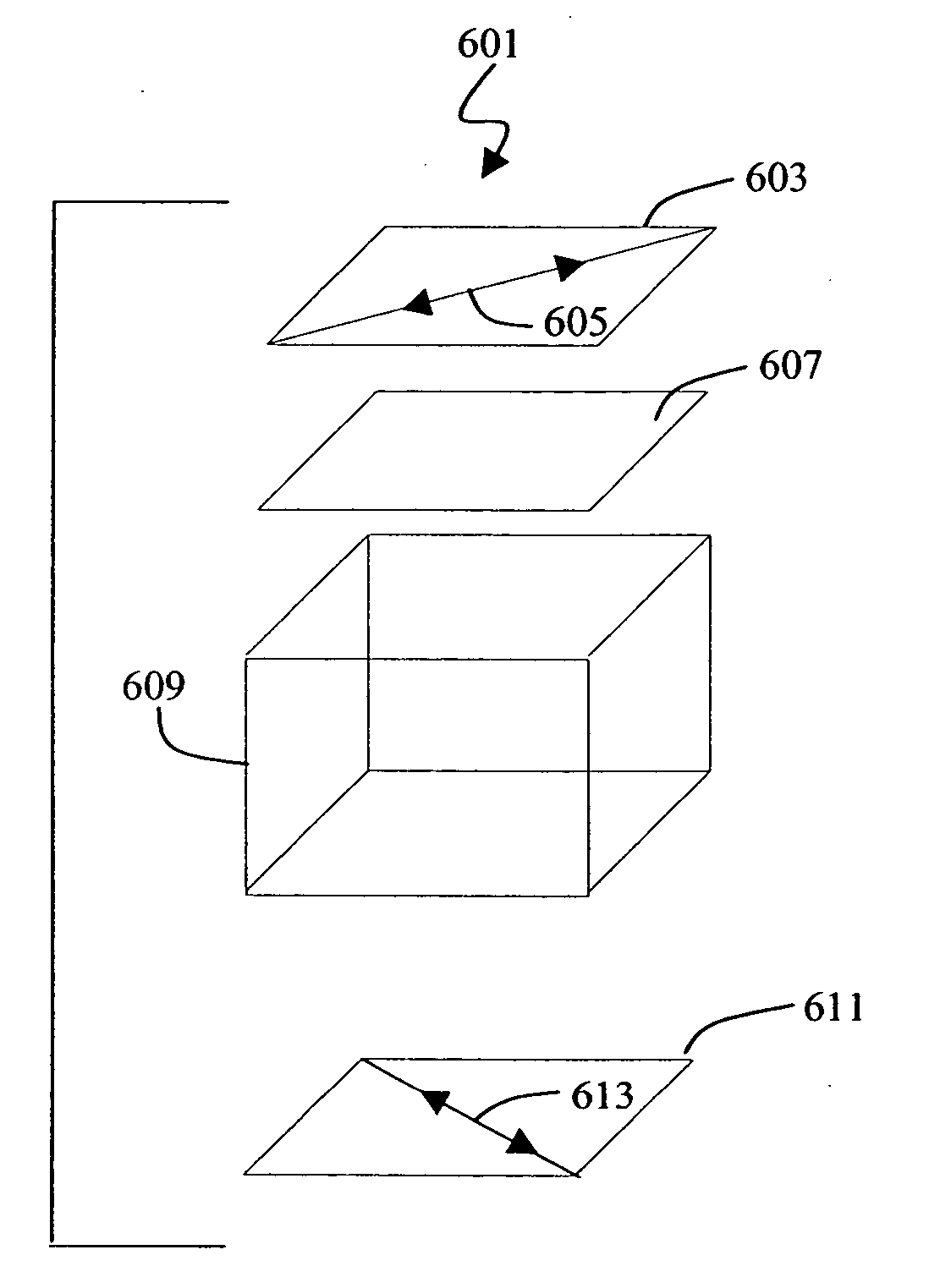
A multilayer optical compensation film includes at least one optically anisotropic first layer and at least one optically anisotropic second layer. The indices of refraction of the first layer satisfies the relation nx1≧ny1≧nz1. The second layer includes amorphous polymer with a glass transition temperature above 160 C.°, and the indices of refraction of the second layer satisfy the relations |nx2−ny2|<0.001 and nz2−(nx2+ny2) / 2>0.005.
Description
FIELD OF THE INVENTION [0001] The present invention generally relates to optical compensation films and to liquid crystal displays containing optical compensation films. More particularly, the present invention relates to an optical compensations film containing two or more optically anisotropic layers, to a liquid crystal display containing an optical compensation film, and to a process of forming an optical compensation film. BACKGROUND OF THE INVENTION [0002] In liquid crystal display (LCD) systems, a liquid crystal cell is typically situated between a polarizer and an analyzer. An incident light polarized by the polarizer passes through a liquid crystal cell and is affected by the molecular orientation of the liquid crystal material, which can be altered by the application of a voltage across the cell. The altered light then enters the analyzer. By employing this principle, the transmission of light from an external source, including ambient light, can be controlled. The energy ...
Claims
Login to View More Application Information
Patent Timeline
 Patent Type & AuthorityApplications(United States)
IPC IPC(8): G02B5/30G02F1/13363G02F1/1343
CPCG02F1/133634G02B5/3083G02F1/13363G02B5/30
InventorISHIKAWA, TOMOHIROELMAN, JAMES F.TEEGARDEN, DAVID M.
OwnerNITTO DENKO CORP