Method and Apparatus for Prevention of Compressor Stall and Combustion Flameout in a Turbine Engine

a turbine engine and compressor technology, applied in mechanical equipment, machines/engines, sustainable transportation, etc., can solve the problems of sudden increase in shaft speed, combustion process flameout, etc., to prevent compressor stall or loss of combustion conditions, prevent excessively rapid increase or decrease in fuel delivery, and prevent excessive change in fuel delivery

Inactive Publication Date: 2005-12-15
PEARCE KEVIN P
View PDF9 Cites 21 Cited by
  • Summary
  • Abstract
  • Description
  • Claims
  • Application Information

AI Technical Summary

Benefits of technology

[0005] The objective of this invention is to prevent compressor stall or loss of combustion conditions by preventing an excessively rapid increase or decrease in fuel delivery to the engine regardless of the rate of change of the demand signal to the fuel control system. Preventing an excessive rate of change in the fuel delivered to the engine eliminates the need for pressure taps and sensors, exhaust gas temperature monitoring equip...

Problems solved by technology

One of the limitations in variable speed applications of turbine engines such as are utilized in aircraft during takeoff and landing, for example, is the problem of either creating a condition commonly referred to as compressor sta...

Method used


Image

  • Method and Apparatus for Prevention of Compressor Stall and Combustion Flameout in a Turbine Engine
  • Method and Apparatus for Prevention of Compressor Stall and Combustion Flameout in a Turbine Engine
  • Method and Apparatus for Prevention of Compressor Stall and Combustion Flameout in a Turbine Engine

Examples


Embodiment Construction

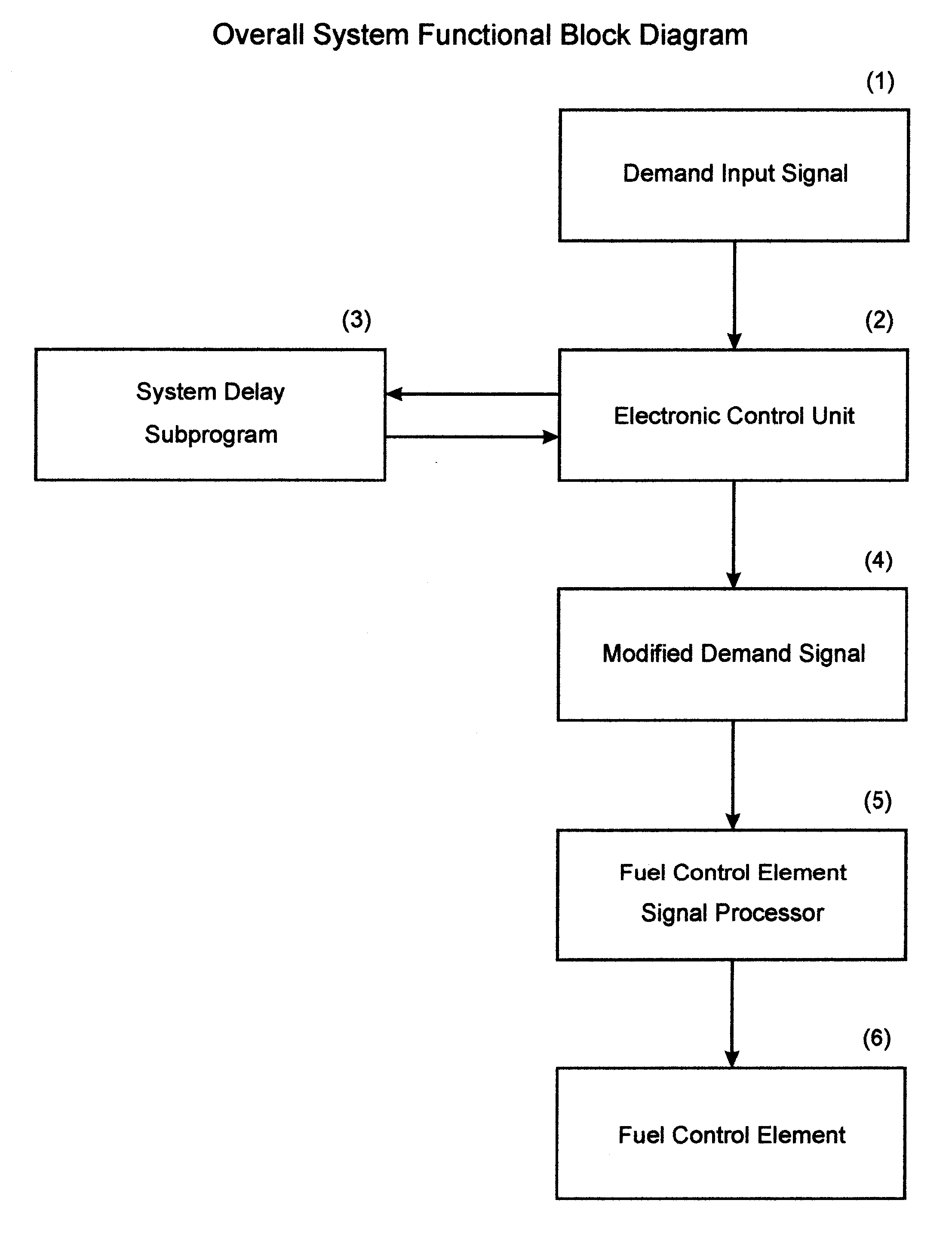
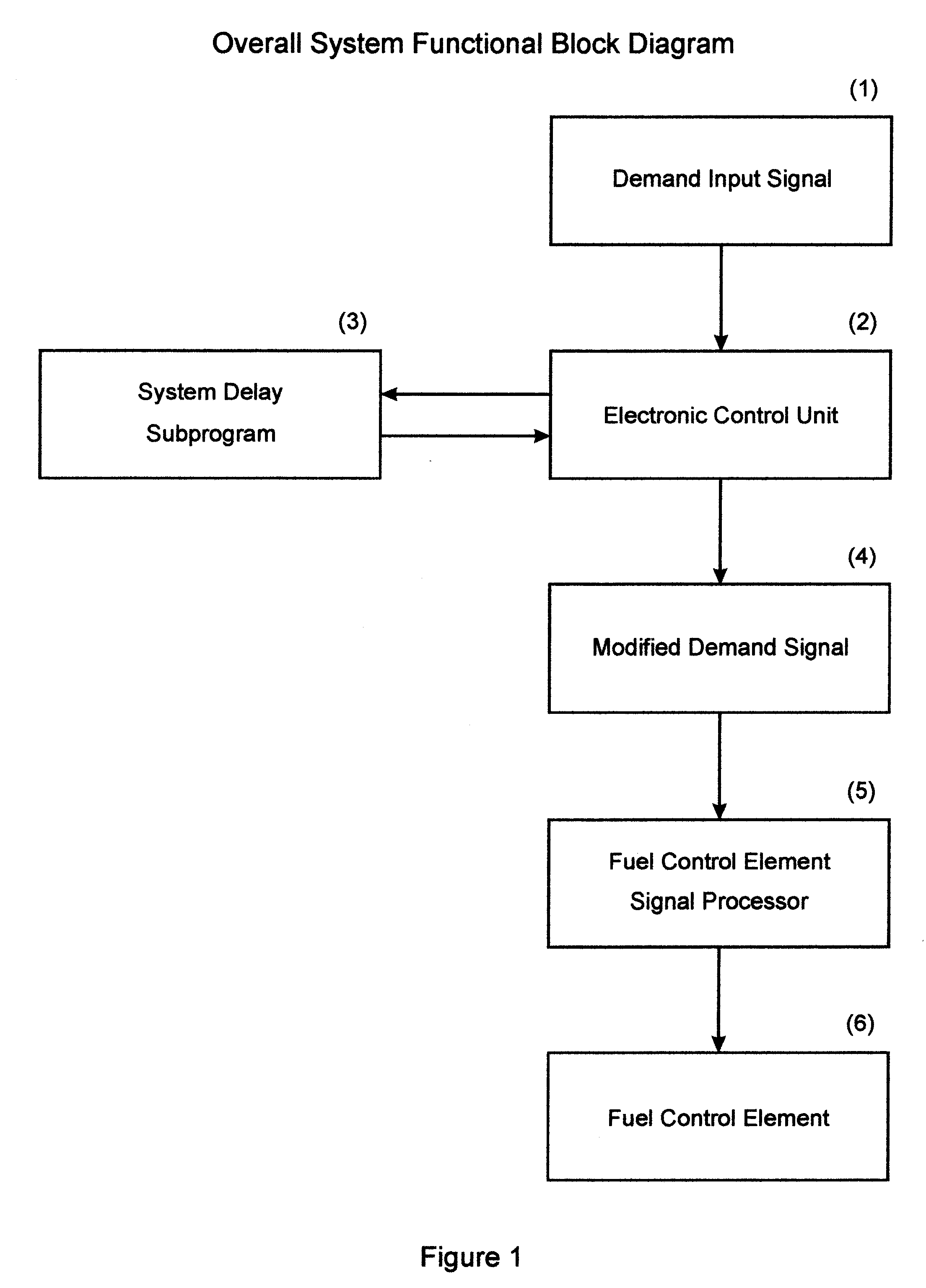
[0010] Referring to FIG. 1 which depicts the interaction of the Electronic Control Unit 2 with the other component parts of the overall fuel supply system. The overall fuel supply system needs, as the first step in control, to be provided a Demand Input Signal 1 from some external source. Depending upon the application, this signal will be from some external source such as a manually controlled throttle to indicate a power set point, a speed signal to indicate a desired RPM level, a temperature signal, or any similar source to provide some desired overall operating characteristic of the engine. Once the signal is converted into an input that the Electronic Control Unit 2 is capable of operating upon, the Electronic Control Unit 2 interfaces with the System Delay Subprogram 3, said System Delay Subprogram being either a portion of the Electronic Control Unit 2 or a separate system which is capable of interacting with the Electronic Control Unit 2 as desired. The Electronic Control Un...


PUM


Abstract

This invention is a means for preventing loss of flame and compressor section instability in a turbine engine. The invention uses an Electronic Control Unit to modify the fuel system demand signal to the final controlling element or elements of a turbine engine to prevent rapid changes either for increasing or decreasing the amount of fuel to the engine. The invention offers the simplicity and reliability of electronic control over previously used mechanical means such as dashpots, variable orifices, springs, and cams. The use of an electronic delay means further allows for reduction in the weight of the overall engine due to elimination of the mechanical apparatus, the ability to change the delay constants in a simple fashion by changing a preprogrammed value rather than physically changing the mechanical hardware, and the ability to have one or more differing delay rates for increasing or decreasing fuel delivery and operating conditions.

Description

BACKGROUND OF INVENTION [0001] One of the limitations in variable speed applications of turbine engines such as are utilized in aircraft during takeoff and landing, for example, is the problem of either creating a condition commonly referred to as compressor stall when the quantity of fuel delivered is increased too rapidly or causing flameout of the combustion process when the quantity of fuel delivered is decreased too rapidly. [0002] Various means have been used to attempt to predict the onset of compressor stall by monitoring some function of the engine. U.S. Pat. No. 3,938,319 (“Method and Apparatus for Preventing Compressor Stall in a Gas Turbine Engine”) senses the pressure differential across a stage or stages of the compressor. An indication of impending compressor stall is a rapidly fluctuating pressure gradient between the intake and exhaust of a stage of the compressor caused by air moving in a laminar flow stream in the un-stalled condition and a turbulent flow stream d...

Claims


Application Information

Patent Timeline
IPC IPC(8): F02C9/30F02C9/32F02C9/28
CPCF02C9/28F02C9/30F02C9/32Y02T50/671F05D2270/10F05D2270/708F05D2270/54F05D2270/309F05D2270/04Y02T50/60
Inventor PEARCE, KEVIN P.
Owner PEARCE KEVIN P
Why Eureka
Try Eureka