Heat-pipe engine structure

a technology of engine structure and heat pipe, which is applied in the direction of indirect heat exchangers, heat exchange apparatus, lighting and heating apparatus, etc., can solve the problems of limiting the application of evaporator and condenser, affecting the horizontal flow of fluid, and unable to truly effectively conduct the fluid between two phases, etc., to achieve better heat conduction effect, flat structure, and wide application range

Inactive Publication Date: 2005-12-15
A LOOPS THERMAL SOLUTION CORP
View PDF8 Cites 16 Cited by
  • Summary
  • Abstract
  • Description
  • Claims
  • Application Information

AI Technical Summary

Benefits of technology

[0019] It is therefore a primary object of the present invention to provide a heat-pipe engine with porous structure. The heat-pipe engine structure includes a metal mesh laminate composed of at least two metal meshes enclosed in a housing. The metal mesh laminate forms a micro-porous structure having numerous meshes which are evenly densely distributed in the housing. The fluid is evenly contained in at least a part of the meshes of the metal mesh laminate for more effective heat-exchange. Therefore, the working fluid is more quickly changed between two phases. In addition, the heat-pipe engine has flat structure and can be made with lightweight and minitype for wider application. A liquid ingress and a vapor egress are formed on the housing of the heat-pipe engine in different positions for externally connecting with a loop heat-pipe for one-way circulation of incoming liquid and outgoing vapor. Accordingly, a better heat conduction effect can be achieved.

Problems solved by technology

Therefore, it is hard to truly effectively conduct the fluid to change between two phases.
Due to gravity, such design limits the application of the evaporator and the condenser.
Such design tends to seriously interfere with horizontal flowing of the fluid.
Moreover, the difficulty in processing and cost for the processing are higher.
This is not so cost-effective.
The meniscus in the evaporator wick result capillary pressure will equal to the total system pressure drop, but powder metallurgy process also disturb the outgas process, that is, it can not be mass-produced for outgas process with powder metallurgy.
Therefore, it is hard to mass-produce the products with unified quality.
Furthermore, it is hard to control the thickness of the housing structure and the distribution of the internal powder is more complicated.
Therefore, the yield is low.
The design of system reaction efficiency is often neglected.
Such structural design leads to limitation of design of evaporator and reservoir or compensation chamber.
While successfully challenging high power, it is impossible to mobilely deal with various heat changes.
Therefore, such structure has poor presentation in thermodynamics, especially low-power thermodynamics.
With respect to the application of an existent CPU, the CPU cannot accept the heat cooler which can only deal with 200 W heat dissipation, while being unable to solve 20 W problem.
The change of room temperature will inevitably affect the effect.
When sintering the metal particles, the particles can be hardly evenly distributed.
Therefore, the quality of the product cannot be unified.
Therefore, the heat conduction effect can be hardly enhanced.
Moreover, the thick heat conductor causes unexpected heat transfer.
Therefore, the heat conductor can hardly receive the pressure of saturated vapor generated after the working fluid absorbs the heat.
As a result, the temperature is apt to abruptly increase and the heat dissipation effect is poor.
Therefore, the heat dissipation effect is quite limited.

Method used


Image

  • Heat-pipe engine structure
  • Heat-pipe engine structure
  • Heat-pipe engine structure

Examples


Embodiment Construction

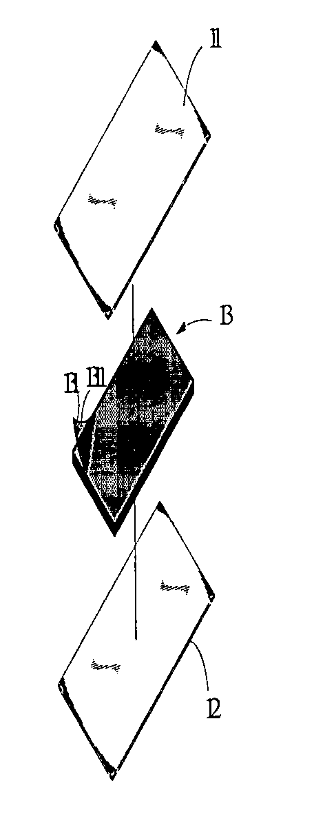
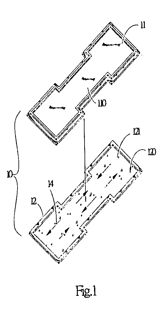
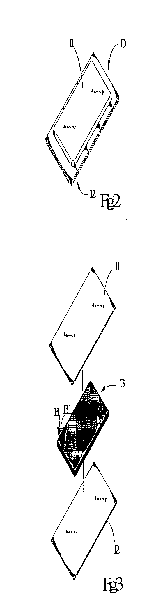
[0032] Please refer to FIGS. 2, 3 and 4. The heat-pipe engine of the present invention includes a housing 10, a metal mesh laminate 13, a fluid 14 and a vapor chamber 15A.

[0033] The metal mesh laminate 13 is formed of one single metal mesh folded into multiple layers. Alternatively, the metal mesh laminate 13 can be composed of more than two metal meshes 131 which are tightly laminated with each other. The metal mesh 131 is formed of metal wires which longitudinally and transversely intersect each other to evenly form numerous meshes. After the metal meshes are laminated, more or several times meshes will be formed between the laminated metal meshes.

[0034] The housing 10 is composed of an upper metal film 11 and a lower metal film 12. The peripheries of the upper and lower metal films 11, 12 are connected and sealed. The upper and lower metal films 11, 12 are respectively bonded to and connected with upper and lower faces of the metal mesh laminate 13. After the peripheries of the...


PUM


Abstract

A heat-pipe engine structure applicable to heat-exchange system. The heat-pipe engine structure includes a metal mesh laminate composed of more than two metal meshes which are tightly laminated with each other to form numerous meshes several times the unlaminated meshes of any original metal mesh. An upper metal film and a lower metal film are respectively bonded to upper and lower faces of the metal mesh laminate. The peripheries of the metal films are sealed to form a housing enclosing the metal mesh laminate. The meshes of the metal mesh laminate form a first nature vapor chamber. A liquid ingress and a vapor egress are formed on the periphery of the housing in different positions for externally connecting with a circulating loop to form a loop heat-pipe for one-way circulation of incoming liquid and outgoing vapor. The meshes of the metal mesh laminate are densely and evenly distributed in as the porous space in the housing for effectively conducting the working fluid to achieve better heat evaporation effect. In heat-exchange procedure, the working fluid is quickly changed between two phases to enhance the circulation. The laminated porous meshes form enough capillary pressure that meniscus in the engine wick supports enough pressure to overcome total system pressure drops from loop.

Description

BACKGROUND OF THE INVENTION [0001] The present invention is related to a heat-pipe engine structure applicable to heat-exchange system. The heat-pipe engine structure includes a metal mesh laminate composed of more than two metal meshes which are tightly laminated with each other to form numerous meshes several times the meshes of any original metal mesh. An upper metal film and a lower metal film are respectively bonded to upper and lower faces of the metal mesh laminate. The peripheries of the metal films are sealed to form a housing enclosing the metal mesh laminate. A working fluid is contained in at least a part of the meshes. The fluid-less meshes naturally form vapor chambers communicating with each other. The meshes of the metal mesh laminate are densely and evenly distributed for effectively conducting the working fluid to enhance evaporation effect. In heat-exchange procedure, the working fluid is quickly changed between two phases that enhance the circulation and heat-exc...

Claims


Application Information

Patent Timeline
Patent Type & Authority Applications(United States)
IPC IPC(8): F28F7/00F28D15/04
CPCF28D15/046
Inventor WU, WEN-KUANG
Owner A LOOPS THERMAL SOLUTION CORP
Why Eureka
Try Eureka