Dust containment device for surfacing machines

a technology for surfacing machines and dust containment devices, which is applied in the field of surfacing machines, can solve the problems of undesirable airborne material, worn pad material becoming airborne, and the burnishing pad itself wears down and discharges pad particles, so as to increase the particle containment, and increase the speed

Inactive Publication Date: 2005-12-15
NHANCE
View PDF9 Cites 1 Cited by
  • Summary
  • Abstract
  • Description
  • Claims
  • Application Information

AI Technical Summary

Benefits of technology

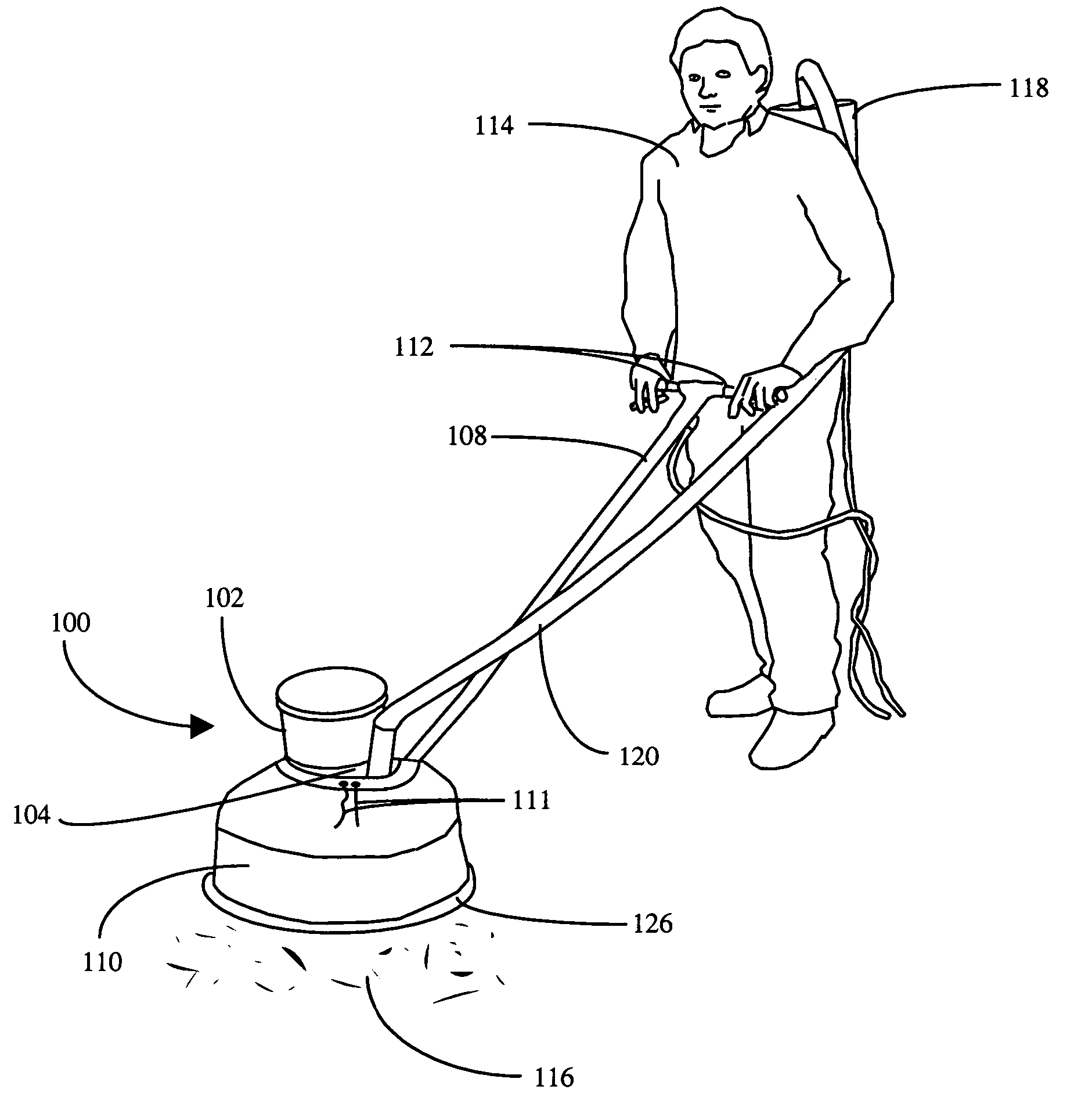
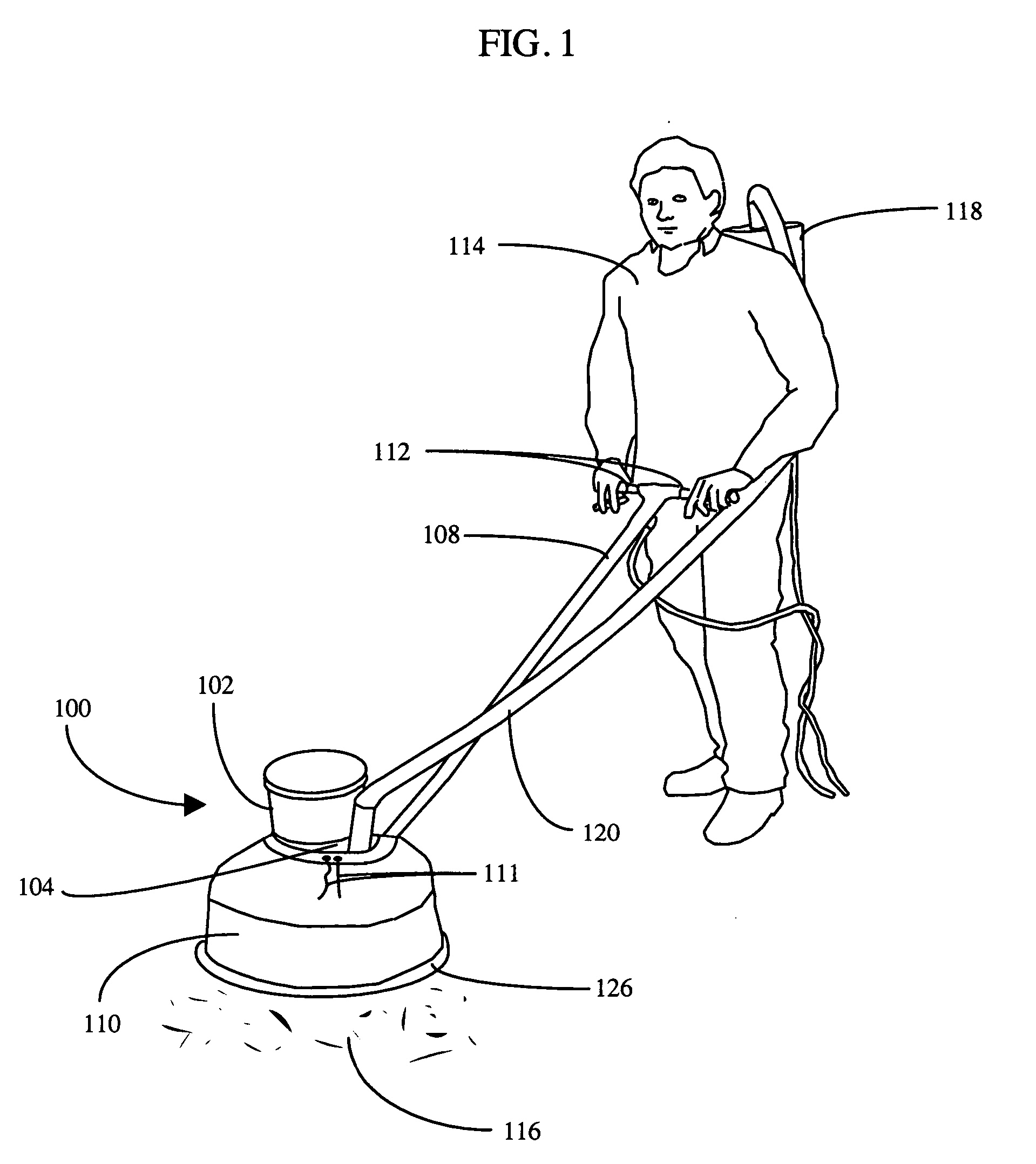
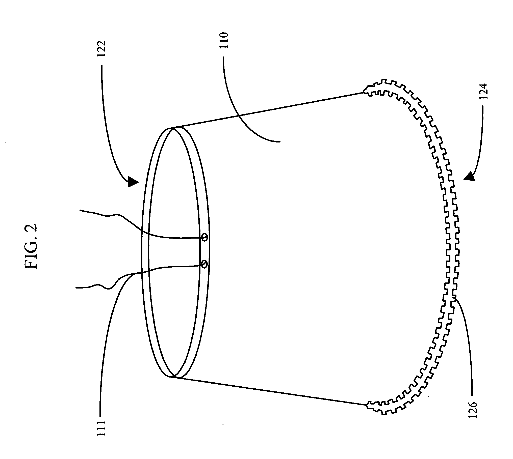
[0010] More specifically, one feature of the present invention relates to a surfacing machine comprising a motor, a body, and a dust containment device. The dust containment device comprises a skirt, which is coupled to the floor machine and forms a cavity over the body and a floor treatment pad. The skirt includes an air channel device secured to a bottom edge of the skirt. The air channel device encircles the floor treatment pad and comprises a multiplicity of slots between a floor and the skirt. Jointly, the skirt and air channel device confine particles within the cavity. A vacuum for sucking the particles from the cavity creates high velocity air flow through the air channel device. Negative pressure within the cavity prevents particles from escaping. The particles are rem

Problems solved by technology

In addition to this powder, the burnishing pad itself wears down and discharges pad particles.
This powder and worn pad material often become airborne because of the air turbulence created by the high speed rotation of the disc.
This airborne material is undesirable because the powder, material, and dust then settle back onto the floor and on furniture and must be removed with a dust mop, vacuum cleaner, or similar means.
Further, the dust that is liberated is particularly noxious.
Left uncontrolled, this dust liberation presents a serious problem.
Floating particles of wood, solvent, water base floor finish, paint, lacquer, and dirt constitute a potentially serious health hazard to c

Method used


Image

  • Dust containment device for surfacing machines
  • Dust containment device for surfacing machines
  • Dust containment device for surfacing machines

Examples


Embodiment Construction

)

[0019] For the purposes of promoting an understanding of the principles of the invention, reference will now be made to the exemplary embodiments illustrated in the drawings, and specific language will be used to describe the same. It will nevertheless be understood that no limitation of the scope of the invention is thereby intended. Any alterations and further modifications of the inventive features illustrated herein, and any additional applications of the principles of the invention as illustrated herein, which would occur to one, skilled in the relevant art and having possession of this disclosure, are to be considered within the scope of the invention.

[0020] Reference throughout this specification to “one embodiment,”“an embodiment,” or similar language means that a particular feature, structure, or characteristic described in connection with the embodiment is included in at least one embodiment of the present invention. Thus, appearances of the phrases “in one embodiment,”“...


PUM


Abstract

A floor machine comprising a motor, a body, and a dust collection system. The dust collection system comprises a skirt, which is coupled to the floor machine and forms a cavity over the body and a floor treatment pad. The skirt includes an air channel device secured to a bottom edge of the skirt. The air channel device encircles the floor treatment pad and comprises a multiplicity of slots between a floor and the skirt. Jointly, the skirt and air channel device confine particles within the cavity. A vacuum for sucking the particles from the cavity creates high velocity air flow through the air channel device. Negative pressure within the cavity prevents particles from escaping. The particles are removed from the cavity through a vacuum tube into the vacuum.

Description

BACKGROUND OF THE INVENTION [0001] 1. The Field of the Invention [0002] The present invention relates to surfacing machines. More particularly, the present invention relates to a device for dust containment for surfacing machines. [0003] 2. The Background Art [0004] High speed burnishing is a floor polishing method using a very fine abrasive disc rotating at 1000 RPM's or more to produce a high “wet look” glass appearance on the floor. Typically a high solids content floor finish material is spread in a thin layer on the floor, allowed to harden, and then burnished with a high RPM burnishing machine. The burnishing process removes the top particles of the floor finish with the fine abrasive rotating disc, producing a smooth glossy appearance. In the process, the top layer of floor finish is removed in the form of a very fine powder. In addition to this powder, the burnishing pad itself wears down and discharges pad particles. This powder and worn pad material often become airborne b...

Claims


Application Information

Patent Timeline
IPC IPC(8): B24B7/18B24B23/00B24B55/10
CPCB24B55/102B24B7/186
Inventor SMITH, TERRANCE C.
Owner NHANCE
Why Eureka
Try Eureka