Electrode device

Inactive Publication Date: 2005-12-15
NTT DOCOMO INC
View PDF3 Cites 11 Cited by
  • Summary
  • Abstract
  • Description
  • Claims
  • Application Information

AI Technical Summary

Benefits of technology

[0024] If a step difference is created between the plurality of electrode sections according to the m

Problems solved by technology

Passive electrode devices, where the amplifier for amplifying myoelectrogram and the electrode section are separated, has a problem that noise easily enters.
The problem here is that myoelectrogram must be measured while suppressing the entry of noise even when the measuring location is outside the shielded room.
Also whe

Method used


Image

  • Electrode device
  • Electrode device
  • Electrode device

Examples


first embodiment

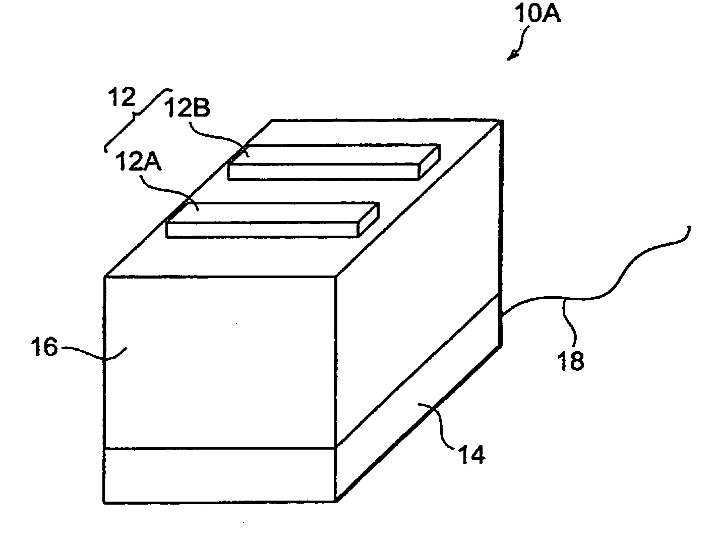
[0039]FIG. 1 shows a configuration example of the electrode device 10A according to the FIG. 1 shows the embodiment when two electrode sections, 12A and 12B, are disposed.

[0040] This electrode device 10A is a so-called active electrode, and comprises an electrode section 12, a flexible section 16, a preamplifier section 14 and a cable for external connection 18. The preamplifier section 14 further comprises a hard preamplifier base and a case for protecting the base. The flexible section 16 is made of material which is non-conductive and transformed flexibly, such as silicon and non-conductive rubber. The electrode section 12 further comprises the electrode sections 12A and 12B made of silver or silver chloride, for example. Each one of the electrode sections 12A and 12B and the preamplifier section 14 are wired by a lead wire (described later with reference to FIGS. 5A, 5B), which is wired inside the flexible section 16. By the cable for external connection 18, power is supplied t...

second embodiment

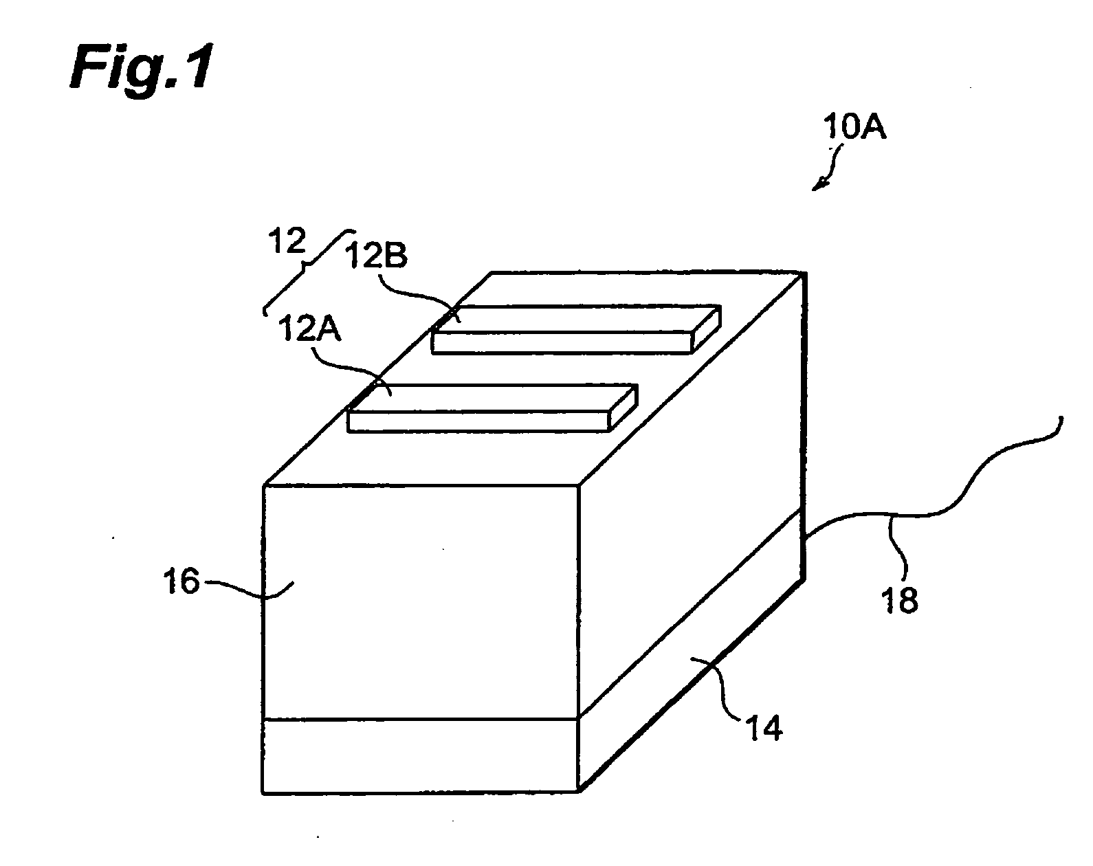
[0042]FIG. 2 shows a configuration example of the electrode device 10B according to the

[0043]FIG. 2 shows the embodiment when three electrode sections, 12A, 12B and 12C, are disposed. Generally it is necessary to measure the potential difference between the two electrode sections to measure myoelectrogram. Therefore when two electrode sections are disposed, only one type of myoelectrogram can be detected. Whereas in the electrode device 10B shown in FIG. 2, three electrode sections are disposed, so the types of myoelectrogram for the number of combinations when two out of three electrode sections are selected, that is, three types of myoelectrogram, can be detected.

[0044] In this way, in the case of the electrode device 10B of the second embodiment, three electrode sections are disposed and three types of myoelectrogram can be detected, therefore more types of myoelectrogram, than the normal case of two electrode sections, can be detected, and efficient detection processing and an ...

third embodiment

[0046]FIG. 3 shows a configuration example of the electrode device 10C according to the In the embodiment shown in FIG. 3, the outside of the flexible section 16 and the preamplifier section 14 shown in FIG. 1 is covered with a conductive flexible material 20, such as conductive rubber, so as to shield the entire electrode device 10C.

[0047] In the active electrode device to which the present invention is applied, noise may enter between the electrode section and the preamplifier section, since the electrode section and the preamplifier section are somewhat apart. Whereas in the present embodiment, the entry of noise is prevented by shielding the area between the electrode section 12 and the preamplifier section 14. In other words, as FIG. 3 shows, the outside of the preamplifier section 14 and the flexible section 16 is covered with a conductive and flexible material 20, which makes it possible to shield the area between the electrode section 12 and the preamplifier section 14.

[00...


PUM


Abstract

The object is to provide an electrode device which can flexibly follow up the movement of the skin in an active electrode device. In an active electrode device, a flexible section, made of a material which is non-conductive and can be transformed flexibly, is disposed between a preamplifier section which is comprised of a hard preamplifier board and a case for protection thereof, and electrode sections made of silver, silver chloride, or the like. By this, the electrode section can move flexibly and can flexibly follow up the movement of the skin.

Description

BACKGROUND OF THE INVENTION [0001] 1. Field of the Invention [0002] The present invention relates to an electrode device for measuring various bio-signals, such as the myoelectrogram of human muscle. [0003] 2. Related Background of the Invention [0004] Conventional electrode devices for measuring myoelectrogram are classified into passive electrode devices where the electrode section and the amplifier are separate, and active electrode devices where the electrode section and the amplifier are integrated. Passive electrode devices are, for example, a plate electrode, needle electrode and disposable electrode. [0005] Passive electrode devices have been used as conventional electrode devices for medical use and inspection. Passive electrode devices, where the amplifier for amplifying myoelectrogram and the electrode section are separated, has a problem that noise easily enters. Also in order to decrease the contact impedance between the electrode section and skin, paste or electrolytes...

Claims


Application Information

Patent Timeline
IPC IPC(8): A61B5/296
CPCA61B2562/164A61B5/0492A61B2562/0215A61B5/296
Inventor MANABE, HIROYUKIHIRAIWA, AKIRAHIRAIWA, YUMIKO
Owner NTT DOCOMO INC
Why Eureka
Try Eureka