Supercharged intercooled engine using turbo-cool principle and method for operating the same

a technology of intercooling engine and supercharger, which is applied in the direction of combustion engine, machine/engine, electric control, etc., can solve the problems of reducing the efficiency of turbocharged si engine, and reducing the efficiency of turbocharged engine. , to achieve the effect of superior engine operation and optimal control of engine operation

Inactive Publication Date: 2005-12-22
LIN SHU WANG
View PDF13 Cites 35 Cited by
  • Summary
  • Abstract
  • Description
  • Claims
  • Application Information

AI Technical Summary

Benefits of technology

[0011] Accordingly, the present invention is made to solve the above-mentioned problems and limitations in the prior art. The present invention provides a supercharged intercooled engine utilizing the turbo-cool principle and methods for operating the same. It is an object of the invention to provide for the simultaneous controlling of both load and speed control and conditioning of intake air in such engines so as to provide superior engine operation. It is a further object of the invention to provide a first operation control unit primarily for speed control, a second operation control unit primarily for conditioning intake air, and an operation control means for controlling a start-of-combustion. It is another object of this invention to provide a method for operating an internal combustion engine including the steps of simultaneously controlling load-and-speed and condition of intake air temperature through the combined application of a first operation control unit, primarily for load-and-speed control, and a second operational control unit, primarily for intake air conditioning. It is also an object of this invention to provide an engine management method for optimally controlling engine operation through the use of an engine management mapping-algorithm.
[0015] The optimum setting of turbo-cooler valve for each given throttle butterfly setting in the SI engine model is determined by testing. Correspondingly, the optimum setting of turbo-cooler valve for each given fuel rate setting in the diesel engine is also determined by testing. The combined application of the primary load / speed control and the primary intake air temperature control allows the engine of the present invention to operate at each steady-state speed and load with intake air in a “sweet spot” of charge-air temperature and pressure, producing unsurpassed performance in thermal efficiency and power.
[0016] Significant gains in both thermal efficiency and power density (extraordinary gain in the case of SI engines) of the proposed engine technology form a powerful combination with superior synergistic potential in fuel economy improvement for automotive use, producing unsurpassed performance at reasonable cost.
[0017] The capability to simultaneously control engine load / speed and intake air temperature at optimal values over a broad range of loads and speeds has an additional application. One of the most promising engine technologies that has emerged over the past few years is called the homogeneous charge compression ignition (HCCI) engine. The combustion process for the HCCI engine is fundamentally different from SI or diesel combustion in the form of spontaneous flameless combustion. The low temperature spontaneous flameless combustion produces very low NOx and particulate matter (PM) emissions combined with high, diesel-like efficiency under ideal conditions. This combination of low emissions and high efficiency explains the excitement generated by the prospect of HCCI.

Problems solved by technology

However, the power boosting in the case of SI gasoline engines is curtailed by knock limits, and, in the case of diesel engines, by mechanical and thermal load limits.
Furthermore, the efficiency of turbocharged SI engines suffers as a result of measures that are necessary for knock avoidance.
Engine operating pressure and temperature approach these limits at high speed and torque load, as a result of excessive energy in the exhaust charge under these operating conditions.

Method used


Image

  • Supercharged intercooled engine using turbo-cool principle and method for operating the same
  • Supercharged intercooled engine using turbo-cool principle and method for operating the same
  • Supercharged intercooled engine using turbo-cool principle and method for operating the same

Examples


Embodiment Construction

[0028] Hereinafter, preferred embodiments of the present invention will be described with reference to the accompanying drawings. In the following description of the present invention, a detailed description of known functions and configurations incorporated herein will be omitted to keep the subject matter of the present invention clear.

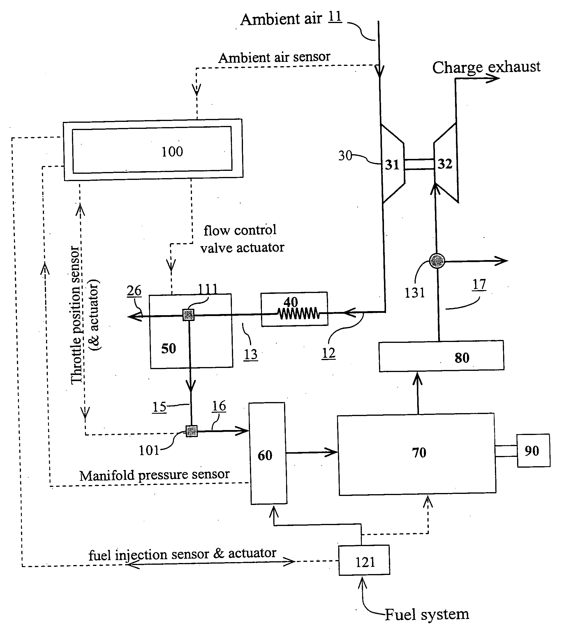
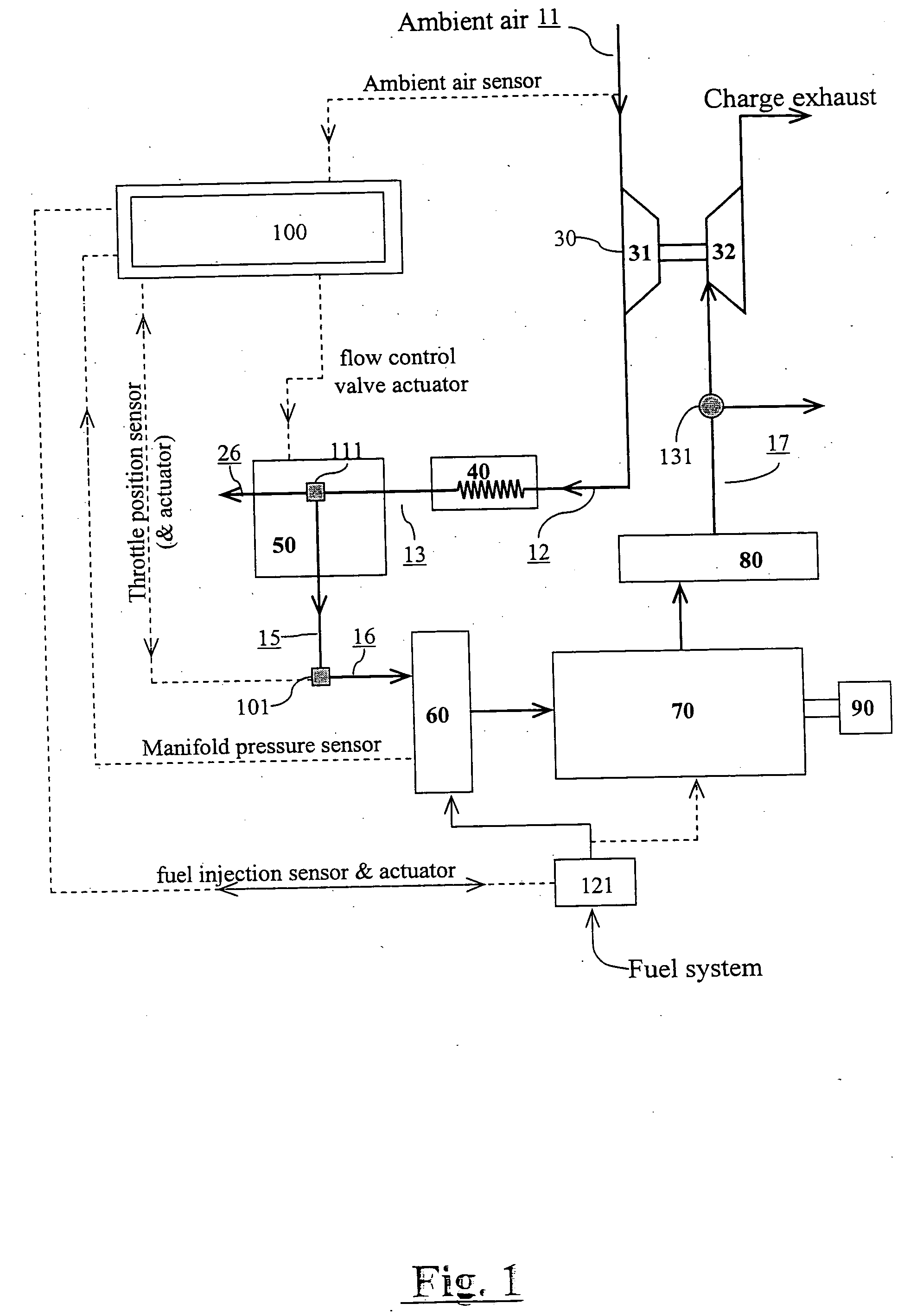
[0029] A supercharged intercooled engine in accordance with turbo-cooling principle is depicted in FIG. 1. An ambient air stream 11, characterized by temperature T0 and pressure P0, enters the compressor 31 of a turbocharger unit 30. Therein air stream 11 is pressurized such that its temperature and pressure are increased to T1 and P1, exiting compressor 31 as air stream 12. Air stream 12 is in communication with an intercooler 40. Intercooler 40 is a heat exchanger, wherein air stream 12 is cooled by an ambient coolant (not shown) to a temperature T2, exiting as air stream 13. The pressure of air stream 13, P2, is only slightly lower than P1 as a ...


PUM


Abstract

A supercharged and intercooled engine utilizing the turbo-cool principle and a method for operating the same is provided. The classical Carnot-Otto-Diesel paradigm for internal combustion engines is modified so internal combustion engines achieve highest performance in an optimal peak temperature range, which is lower than the typical peak operation temperatures of current gasoline engines and diesel engines. Turbo-cooling turbocharging systems provide for internal combustion engines operating within this peak temperature range by simultaneously controlling engine load-and-speed and intake-air temperature through the combined application of a primary load-and-speed control and a second operation control unit, primarily for intake air conditioning. This can be applied to gasoline engines, diesel engines, direct-injection gasoline engines, and homogeneous charge compression ignition (HCCI) engines.

Description

PRIORITY [0001] This application claims priority to a provisional application entitled “Turbo-Cool: The Turbo-Cooling Principle of Internal-Combustion Engines” filed in the US Patent Office on Jul. 22, 2004 and assigned U.S. patent application Ser. No. 60 / 590,100 and to a provisional application entitled “The Turbo-Cooling Principle of Internal Combustion Engines” filed in the US Patent Office on Jun. 17, 2004 and assigned U.S. Pat. No. 60 / 580,493.BACKGROUND OF THE INVENTION [0002] 1. Field of the Invention [0003] The present invention relates generally to supercharged internal combustion engines. Specifically, the present invention is directed to a turbocharged-intercooled engine, which may be a homogeneous charge spark ignition (SI) type, a heterogeneous charge compression ignition (diesel) type, a heterogeneous charge (direct-injection) spark ignition type, or homogeneous charge compression ignition (HCCI) type. [0004] 2. Description of the Related Art [0005] H. R. Ricardo stated...

Claims


Application Information

Patent Timeline
Patent Type & Authority Applications(United States)
IPC IPC(8): F02B1/12F02B3/06F02B29/04F02B33/44F02B75/12F02D9/02F02D23/00F02D41/00
CPCF02B1/12F02B3/06F02B29/0425F02B29/0481F02B33/44F02B2075/125Y02T10/144F02D41/0007F02D2009/0283Y02T10/128Y02T10/146Y02T10/123F02D23/00Y02T10/12
Inventor WANG, LIN-SHUYANG, SHIYOU
Owner LIN SHU WANG
Why Eureka
Try Eureka