Load bearing surface

a technology of load bearings and surface layers, applied in the field of load bearing surfaces, can solve the problems of inability to tune the characteristics of conventional molded seats, uncomfortable and sometimes ergonomically unacceptable load bearing surfaces, and inconvenient manufacturing, etc., to achieve the effect of increasing the alignment of the crystalline structure of the elastomeric material, and reducing the cost of manufacturing

Active Publication Date: 2005-12-22
ILLINOIS TOOL WORKS INC
View PDF12 Cites 26 Cited by
  • Summary
  • Abstract
  • Description
  • Claims
  • Application Information

AI Technical Summary

Benefits of technology

[0015] The present invention provides a strong, yet flexible load bearing surface. The elastomeric load bearing surfaces are relatively inexpensive to manufacture, and provide a light weight surface that can be ventilated to inhibit heat retention. The decoupled elastomeric material exhibits support characteristics that are particularly well suited for use in seating applications because it provides different degrees of elasticity and support in different directions. For example, the decoupled elastomeri...

Problems solved by technology

Although these molded chairs provide an inexpensive seating option, they do not provide the level of support and comfort available in more expensive load bearing surfaces, such as conventional cushion sets.
In seating and other body-support applications, this may result in an uncomfortable and sometimes ergonomically unacceptable load bearing surface.
Further, the ability to tune the characteristics of a conventional molded seat is relatively limited.
Different ma...

Method used


Image

  • Load bearing surface
  • Load bearing surface
  • Load bearing surface

Examples


Embodiment Construction

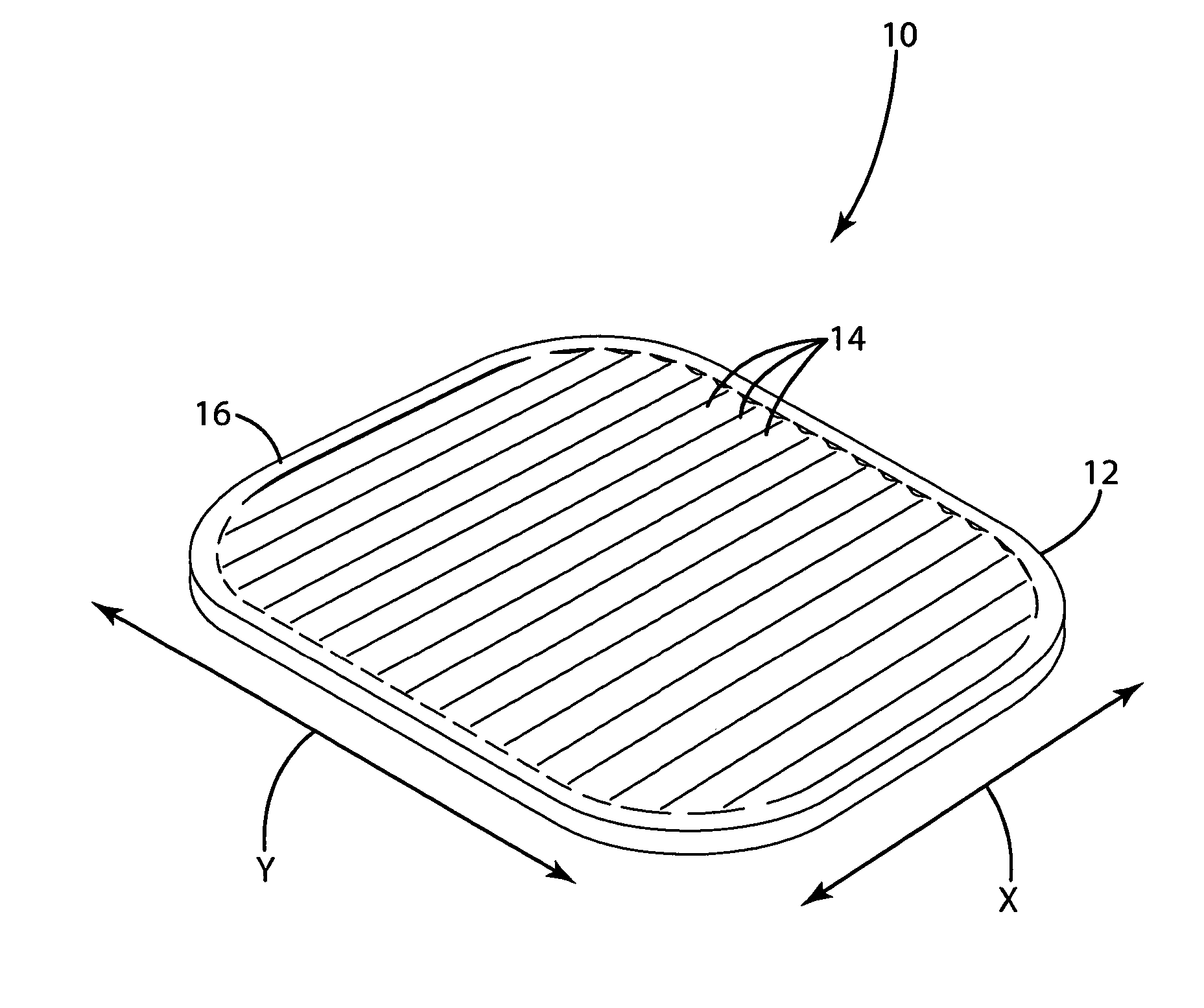
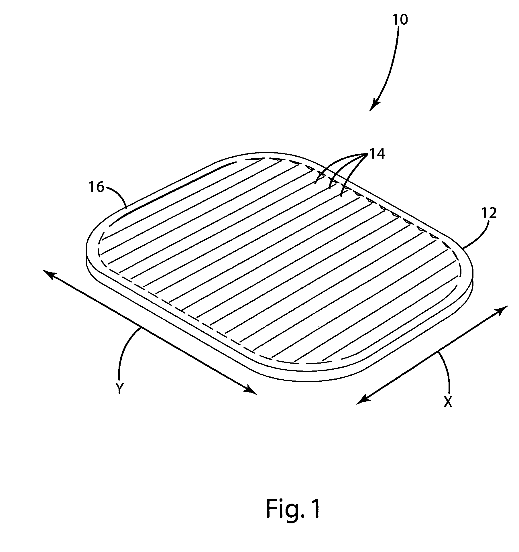
[0042] A load bearing surface 10 according to one embodiment of the present invention is shown in FIG. 1. The load bearing surface 10 shown in FIG. 1 is a molded membrane that may be suspended from a support structure, such a chair seat frame (not shown). The load bearing surface 10 includes support characteristics that differ in different directions. For example, the load bearing surface may provide significant elastic support in the x direction while providing relatively little support in the y direction. This “decoupling” of the support characteristics of the load bearing surface provides a high degree of comfort. By way of disclosure, the present invention is described in connection with various alternative embodiments intended primarily for use in seating applications. The present invention is not, however, limited to use in seating applications, but may also be incorporated into other load bearing applications. The support characteristics of the molded membrane are highly adju...


PUM

PropertyMeasurementUnit
Angleaaaaaaaaaa
Elastomericaaaaaaaaaa
Structureaaaaaaaaaa

Abstract

An elastomeric load bearing surface with different load support characteristics in different directions. In one embodiment, the surface includes an elastomeric membrane that is oriented in only a single direction, for example, by compression or stretching. In another embodiment, the surface includes mechanical structures, such as connectors, variations in thickness and apertures, that vary the load support characteristics in different directions. In another aspect, the present invention provides a multilayer load bearing surface in which the layers cooperate to provide a controlled force/deflection profile that is variable in different regions of the surface. In one embodiment, the upper layer includes a plurality of loosely connected nodes and a lower layer having a plurality of resilient elements that separately support each node.

Description

[0001] This application claims the benefit of U.S. Provisional Application No. 60 / 580,648, filed Jun. 17, 2004.BACKGROUND OF THE INVENTION [0002] The present invention relates to load bearing surfaces, and more particularly to elastomeric load bearing surfaces, such as the seat or back of a chair or bench, or the support surface of a bed, cot or other similar product. [0003] There are continuing efforts to develop new and improved load bearing surfaces. In the context of general load bearing surfaces, the primary objectives of these efforts are to obtain a durable and inexpensive load bearing surface. In the context of seating and other body-support applications, it is also important to address comfort issues. For example, with seating, it can be important to provide a surface that is comfortable and does not create body fatigue over periods of extended use. Given that the load characteristics (e.g. stiffness, resiliency, force / deflection profile) desired in a particular surface wil...

Claims


Application Information

Patent Timeline
IPC IPC(8): A47C5/12A47C7/14A47C7/74A47C27/14
CPCA47C7/746F16F2226/00Y10T428/24975A47C5/12F16F1/36Y10T428/24719A47C7/282A47C7/287A47C7/14A47C7/144B29C55/12B29D7/01
Inventor COFFIELD, TIMOTHY P.SOMMERFIELD, DANIEL S.WARD, JOSEPH D.
Owner ILLINOIS TOOL WORKS INC
Why Eureka
Try Eureka