Torque transmitting unit

Inactive Publication Date: 2005-12-22
SCHAEFFLER TECH AG & CO KG
View PDF4 Cites 27 Cited by
  • Summary
  • Abstract
  • Description
  • Claims
  • Application Information

AI Technical Summary

Benefits of technology

[0016] Another preferred exemplary embodiment of the torque transmitting unit is characterized in that the bearing device is positioned coaxial to and radially outside of the seal device. That creates an easily realized possibility for positioning the bearing device in the interior of the clutch device, which is sealed toward the outside by the seal device.
[0017] Another preferred exemplary embodiment of the torque transmitting unit is characterized in that the bearing device is positioned overlapping the seal device in the axial direction. That makes it possible to save construction space in the axial direction.
[0018] Another preferred exemplary embodiment of the torque transmitting unit is characterized in that the bearing device is positioned in a wet chamber which is bounded by the clutch housing section. That makes it possible to supply the bearing device with lubricant from the wet chamber of

Problems solved by technology

Lever-operated wet clutches have the disadvantage that the operating forces which ar

Method used


Image

  • Torque transmitting unit
  • Torque transmitting unit
  • Torque transmitting unit

Examples


Example

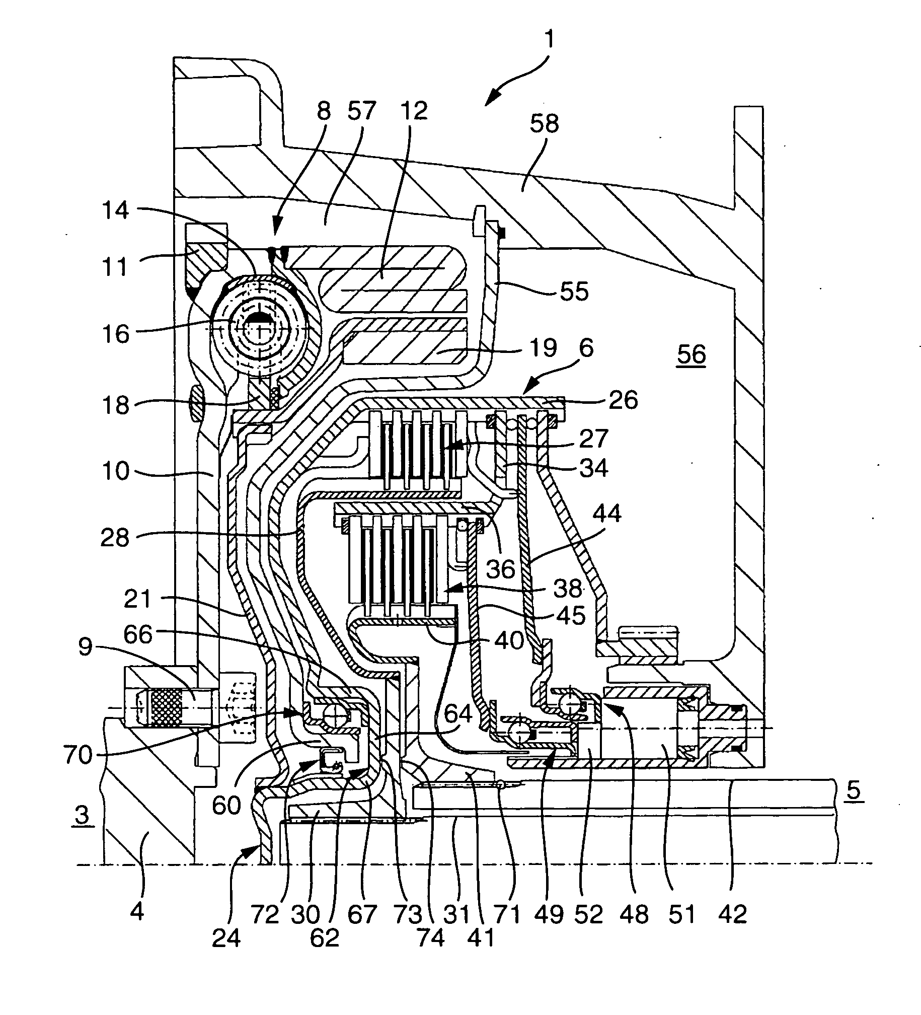
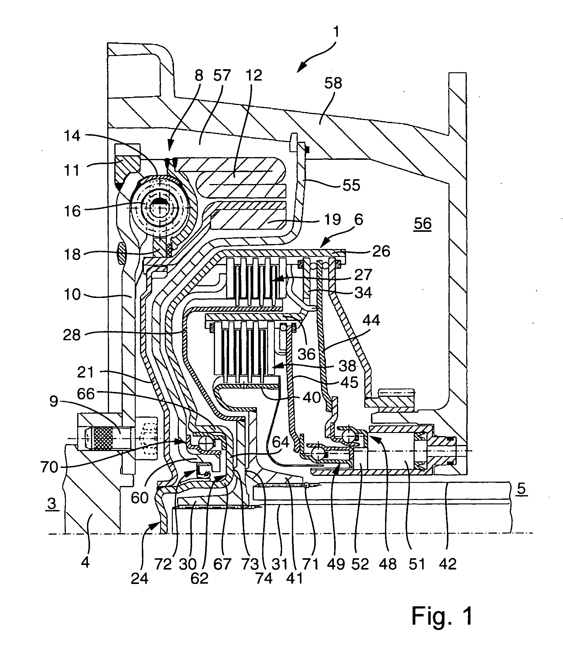
[0027] Part of a power train 1 of a motor vehicle is illustrated in FIG. 1. Positioned between a drive unit 3, in particular a combustion engine, from which a crankshaft 4 extends, and a transmission 5, is a wet operating double clutch 6 of multiple-disk design. Connected between drive unit 3 and double clutch 6 is a vibration damping unit 8. The vibration damping unit is preferably a two-mass flywheel.

[0028] Crankshaft 4 of combustion engine 3 is rigidly connected through a screw connection 9 to an input part 10 of vibration damping unit 8. Input part 10 of vibration damping unit has essentially the form of a circular ring extending in the radial direction, to which a starter gear rim 11 is welded radially on the outside. In addition, a centrifugal mass 12 is welded onto the input part 10 of vibration damping unit 8. Furthermore, attached to input part 10 of vibration damping unit 8 is a vibration damper cage 14, which at least partially incorporates a plurality of energy storage ...


PUM


Abstract

A torque transmitting unit in the power train of a motor vehicle for transmitting torque between a drive unit having an output shaft and a transmission having at least one input shaft. A clutch is positioned between the transmission input shaft and the drive unit output shaft. The clutch includes an input part that has a clutch cover that defines a clutch-containing volume and that is supported by a transmission housing section. In order to limit axial vibrations of the clutch, the clutch input part is axially supported by a bearing.

Description

BACKGROUND OF THE INVENTION [0001] The present invention relates to a torque transmitting unit in the power train of a motor vehicle for transferring torque between a drive unit, in particular a combustion engine, having an output shaft, in particular a crankshaft, and a transmission having at least one input shaft, there being inserted between the transmission input shaft and the output shaft of the combustion engine a clutch device having at least one input part, which has a clutch housing section, in particular a clutch cover, which limits the volume accommodating the clutch device and is supported by a transmission housing section. [0002] The object of the invention is to create a simply constructed and economically manufacturable torque transmitting unit with which fewer vibrations occur in the coupling device in the axial direction than with conventional torque transmitting units. SUMMARY OF THE INVENTION [0003] The object is achieved with a torque transmitting unit in the pow...

Claims


Application Information

Patent Timeline
IPC IPC(8): B60K17/02F16D25/0638F16D25/10
CPCF16D25/10F16D25/0638F16D21/06F16D2021/0661F16D25/087F16H45/02
Inventor AGNER, IVO
Owner SCHAEFFLER TECH AG & CO KG
Why Eureka
Try Eureka