Portable filter system

Active Publication Date: 2005-12-22
BANK OF AMERICA N A
View PDF65 Cites 7 Cited by
  • Summary
  • Abstract
  • Description
  • Claims
  • Application Information

AI Technical Summary

Benefits of technology

[0021] The present systems use the natural ability of the coiled tubular filter configuration to de-emulsify and coalesce oils and makes use of gravity to facilitate separating and accumulating the coalesced oils, in a container, for ease of removal. A present system can be provided in a modular design having a relatively small footprint, which provides a cost effective, machine-dedicated system for example, for parts cleaners, machine tools and the like. Moreover, the present de-emulsifying/coalescing coiled tubular filter system i

Problems solved by technology

As a result of the two outlet system, the floating oil accumulating in the filter canister will not be able to exit from the filter canist

Method used


Image

  • Portable filter system
  • Portable filter system
  • Portable filter system

Examples


Embodiment Construction

[0041] While the present invention is susceptible of embodiment in various forms, there is shown in the drawings a number of presently preferred embodiments that are discussed in greater detail hereafter. It should be understood that the present disclosure is to be considered as an exemplification of the present invention, and is not intended to limit the invention to the specific embodiments illustrated. It should be further understood that the title of this section of this application (“Detailed Description of the Invention”) relates to a requirement of the United States Patent Office, and should not be found to limit the subject matter disclosed herein.

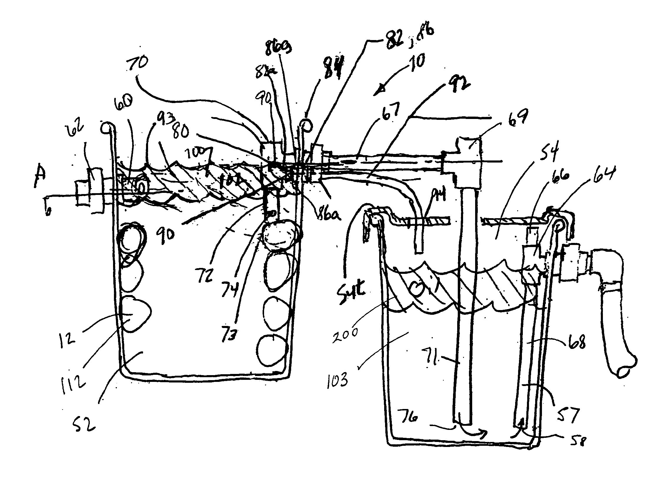
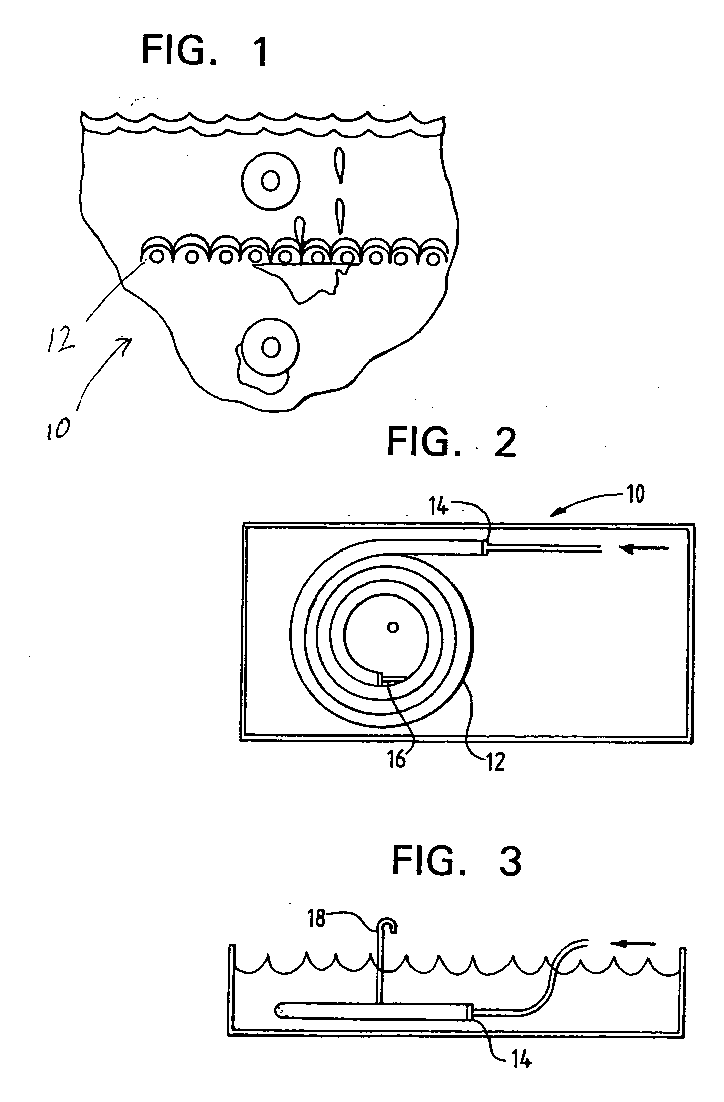
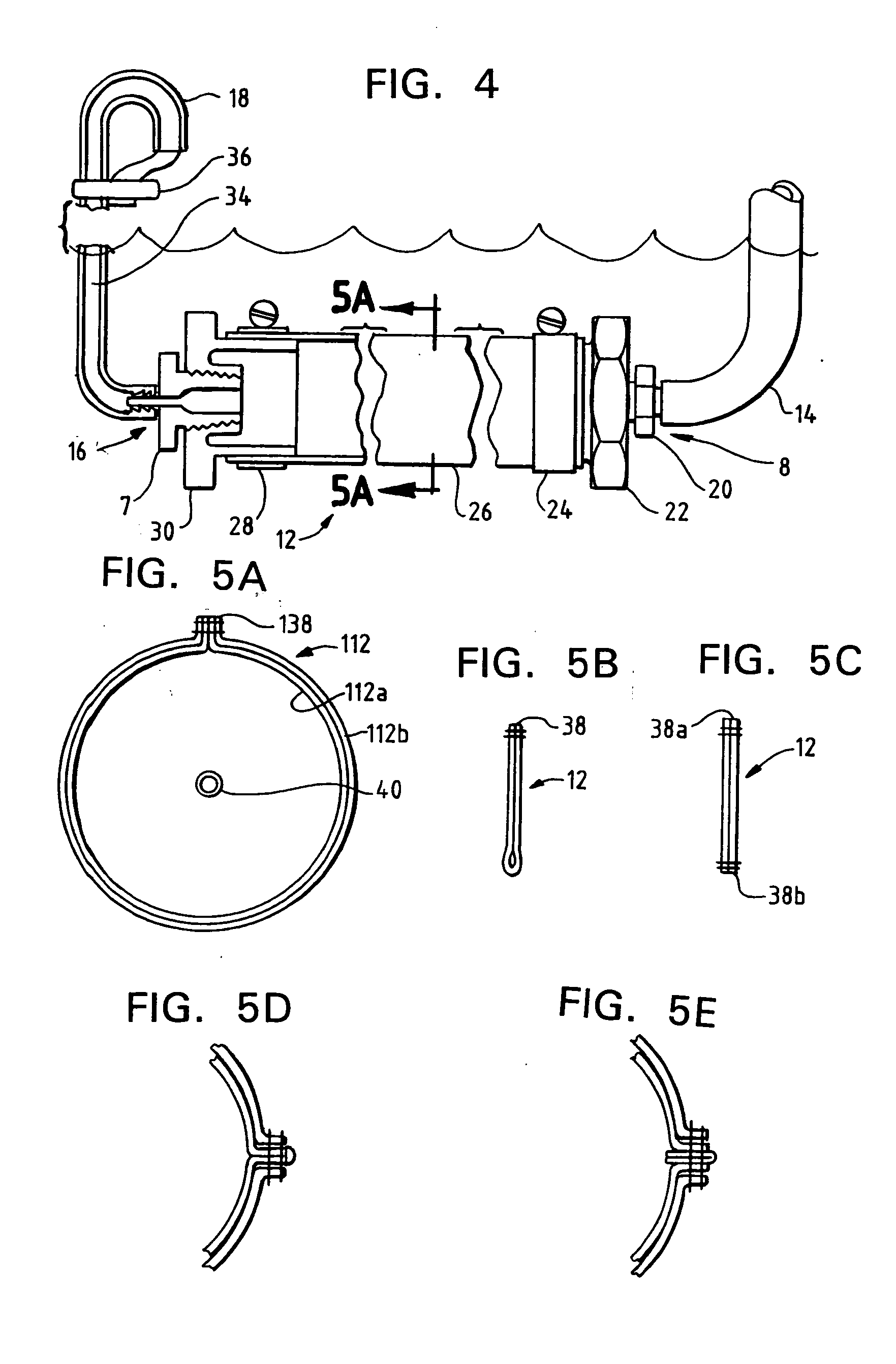
[0042] Referring to the figures, there is shown several embodiments of a de-emulsifying / coalescing coiled tubular filter system 10. The system 10 is configured to receive a contaminated liquid stream, such as an oil-in-water emulsion, de-emulsify the contaminants from the emulsion and pass both the contaminants and the emulsion th...


PUM

PropertyMeasurementUnit
Lengthaaaaaaaaaa
Lengthaaaaaaaaaa
Fractionaaaaaaaaaa

Abstract

A filter system for receiving an aqueous-based fluid contaminated with particles and emulsified contaminant oil, removing the particles, and separating the emulsified contaminant oil from the aqueous-based fluid includes a filter media for receiving the aqueous-based fluid and emulsified contaminant oil, having an inner filter element formed from a 95 percent single pass efficiency 48 micron (5 micron nominal) filtering material of needle punch polypropylene felt, an outer filter element formed from a 95 percent single pass efficiency 19 micron absolute filtering material of a polypropylene microfiber material and a porous spunbond polypropylene sandwiching the outer filter media. The filter element removes particles, de-emulsifies the emulsified contaminant oil from the aqueous-based fluid into the contaminant oil and the aqueous-based fluid, separates the de-emulsified contaminant oil from the aqueous-based fluid, coalesces the separated contaminant oil and passes both the coalesced de-emulsified contaminant oil with entrained particles and the aqueous-based fluid. A first tank supports the filter element and is further configured to hold a quantity of the separated coalesced contaminant oil and the aqueous-based fluid. The first tank has a first outlet passing the aqueous-based fluid from the first tank to near the bottom of the second tank and a second outlet passing the separated coalesced contaminant oil to the top of the second tank. The second tank has an oil separation assembly for separating the aqueous-based fluid from the contaminant oil and passing the aqueous-based fluid therefrom. The second container also has a drain valve assembly for removing only the accumulated coalesced de-emulsified contaminant oil. A method for separating the emulsified contaminant oil from the aqueous-based fluid and recovering the aqueous-based fluid is also disclosed.

Description

FIELD OF THE INVENTION [0001] The present invention concerns a filter device suited for separating oil from water based fluids and filtering particles out of the water based fluids. More particularly the present invention concerns a particle filtration, de-emulsification, oil coalescing, oil collecting and gravity separation system that uses a microfiber polymer filter media in a coiled tubular arrangement in association with means to de-emulsify and separate fluids by density and permit separated fluids to flow separately into a final separation location, such that re-emulsification of the desired fluid with the contaminant is lessened. BACKGROUND OF THE INVENTION [0002] Devices, systems and methods for the removal of particles, free oil (such as dispersed, finely divided oil droplets), and emulsified oil contaminants in aqueous fluids is in widespread use in all types of commercial and industrial facilities. Known devices include cartridge and bag filters either permanently instal...

Claims


Application Information

Patent Timeline
IPC IPC(8): B01D17/00C10M175/00C10M175/04
CPCB01D17/00C10M175/0058C10M175/04C10N2250/021Y10S210/05B01D17/0208B01D17/0214B01D17/045C10N2050/011
Inventor LARSON, DOUG
Owner BANK OF AMERICA N A
Why Eureka
Try Eureka