
System of sampling interface for an optical pick-up head

a sampling interface and optical pick-up head technology, applied in the field of interface circuit systems, can solve the problems of weakened reading voltage and weakened writing voltage that is not for sampling, and achieve the effect of reducing the sampling tim

Inactive Publication Date: 2005-12-22
TIAN HLDG
View PDF16 Cites 7 Cited by
  • Summary
  • Abstract
  • Description
  • Claims
  • Application Information

AI Technical Summary

Benefits of technology

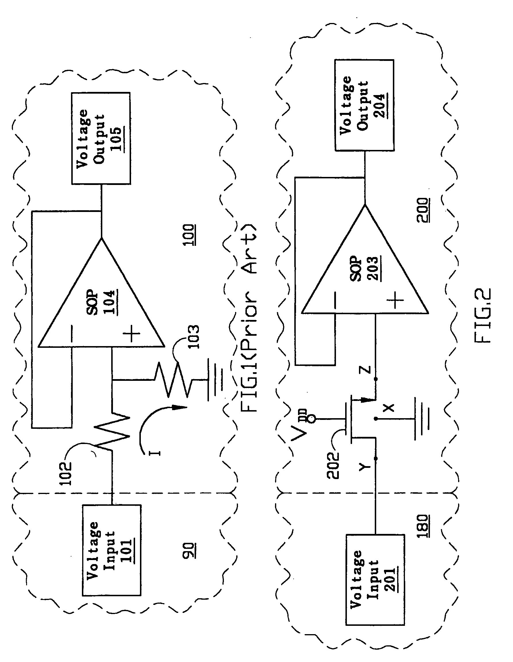
[0007] According to the above-mentioned, the prior art has to supply additional current to drive the resistor. The bigger resistance is, the bigger settling time of the SOP is, so that the sampling time is reduced. Furthermore, not only the writing voltage that is not for sampling is weakened but also the reading voltage that is for sampling is weakened.
[0008] One purpose of present invention is that the voltage divider is replaced by the N-TYPE MOS (NMOS) to reduce the load of the optical pick-up head, and doesn't weaken the reading voltage for enhancing SNR. Furthermore, the settling time of the SOP is reduced so that the sampling time is increased and power consumption is reduced.

Problems solved by technology

Furthermore, not only the writing voltage that is not for sampling is weakened but also the reading voltage that is for sampling is weakened.
Some of the high reading voltage will lead to problems because the specifications of different kinds of optical pick-up heads are not the same.

Method used


Image

  • System of sampling interface for an optical pick-up head
  • System of sampling interface for an optical pick-up head
  • System of sampling interface for an optical pick-up head

Examples


Embodiment Construction

[0017] Some sample embodiments of the invention will now be described in greater detail. Nevertheless, it should be recognized that the present invention can be practiced in a wide range of other embodiments besides those explicitly described, and the scope of the present invention is expressly not limited except as specified in the accompanying claims.

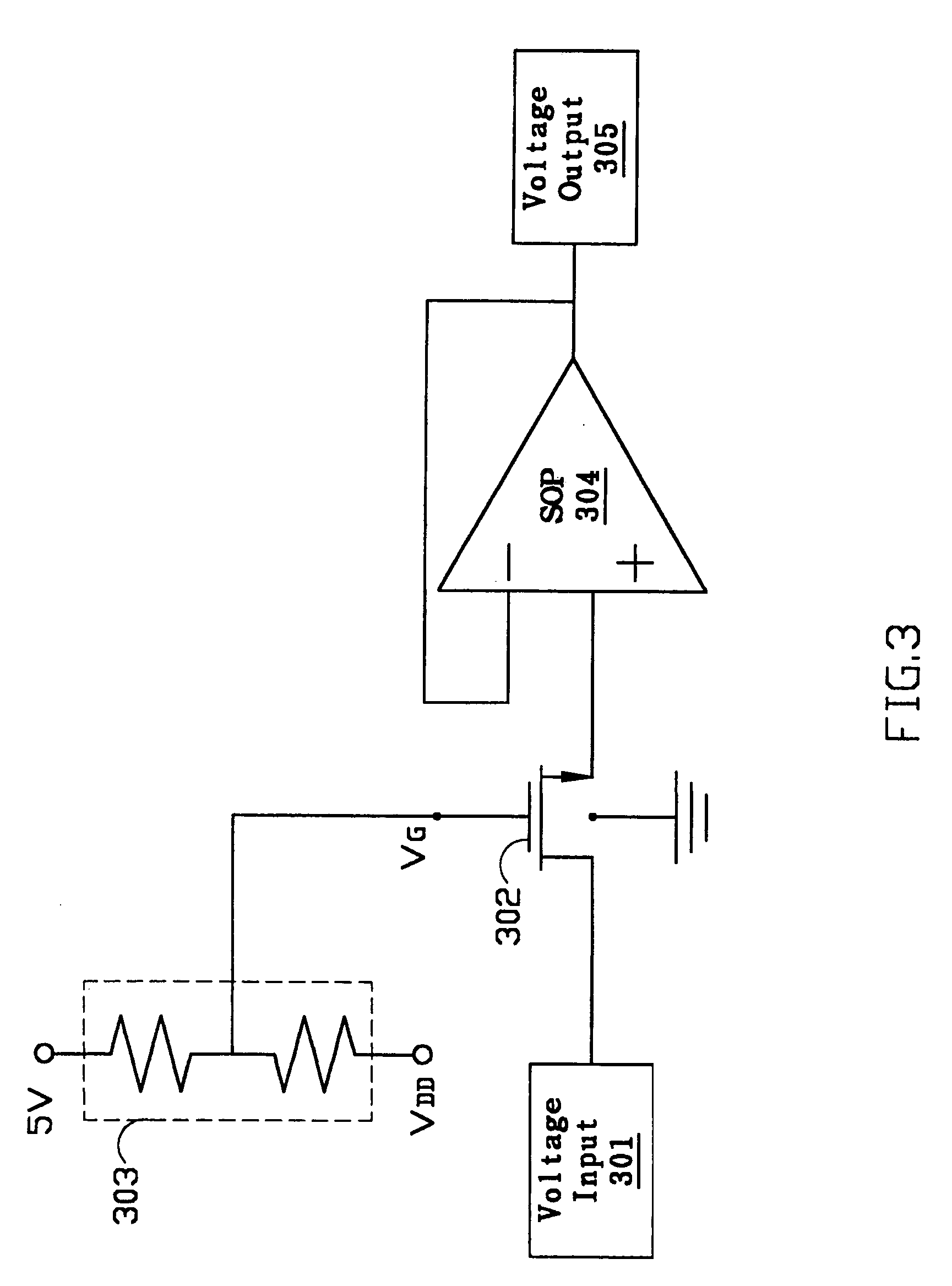
[0018] Referring to FIG. 2 in accordance with an embodiment of the present invention, the voltage input 201 is output by the optical pick-up head 180, this voltage at the minimum could be one of a reading voltage (between 1.4 volts and 2.8 volts) and a writing voltage (between 3.3 volts and 5 volts). A switch circuit (NMOS 202 is a representative) is used as the first path circuit and placed between the optical pick-up head 180 and SOP 203 to receive the reading voltage and writing voltage. The above-mentioned writing voltage and reading voltage could alternately appear. Moreover, the switch circuit such as the NMOS 202 disconnects t...


PUM


Abstract

A system of sampling interface for an optical pick-up head includes an optical pick-up head, a switch circuit and a sample and hold circuit. The optical pick-up head outputs one of a reading voltage and a writing voltage. The switch circuit includes a NMOS. The NMOS has a first source / drain for receiving the reading voltage and the writing voltage, and has a gate for receiving the gate voltage. The NMOS turns on the first source / drain and the second source / drain when receiving the reading voltage, and turns them off when receiving the writing voltage. Finally, a sample and hold circuit connects to the second source / drain of the NMOS for sampling and holding the reading voltage.

Description

BACKGROUND OF THE INVENTION [0001] 1. Field of the Invention [0002] The present invention is generally related to an interface circuit system, and more particularly to a sampling interface circuit for providing the functions of signal sample and hold between the circuits with a different working voltage. And the interface circuit system could protect the circuits with a lower working voltage during the high voltage operation. [0003] 2. Description of the Prior Art [0004] When a signal is transmitted from a circuit with a higher working voltage to a circuit with a lower working voltage, an interface circuit has to exist between the two circuits to weaken the signal to the voltage accepting range of the circuit with a lower working voltage. For example, the working voltage of a general optical pick-up head is 5 volts, and the working voltage of an optical disk driver (CD-ROM) control chip 100 is 3.3 volts. If the writing voltage output by optical pick-up head is directly input into th...

Claims


Application Information

Patent Timeline
IPC IPC(8): G11B7/00G11C27/02
CPCG11C27/02
Inventor LIU, CHIH-MIN
Owner TIAN HLDG
Learn More