
Cardiac harness having radiopaque coating and method of use

Inactive Publication Date: 2005-12-22
PARACOR MEDICAL
View PDF99 Cites 37 Cited by
  • Summary
  • Abstract
  • Description
  • Claims
  • Application Information

AI Technical Summary

Benefits of technology

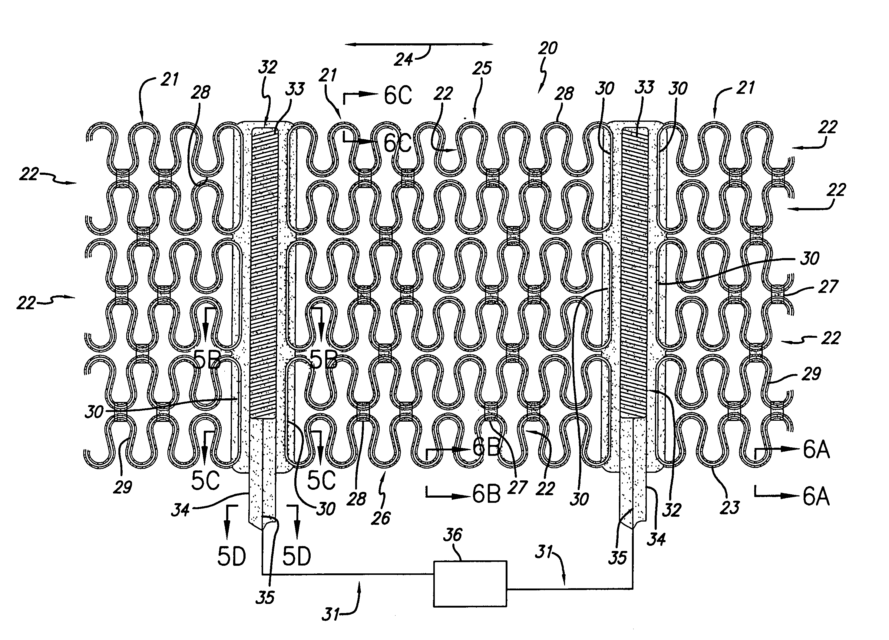
[0009] In keeping with the invention, the cardiac harness was configured to fit at least a portion of a patient's heart and is coated with a dielectric coating or other polymer, preferably to electrically insulate the conductive material from an electric current that may be applied to the heart. In this embodiment, the dielectric coating or other polymer material is loaded with a radiopaque substance that will enhance the visualization of the cardiac harness when viewed under fluoroscopy or other x-ray devices. In one embodiment, the polymer is a silicone rubber that is loaded with a barium sulfate compound in order to increase the radiopacity of the silicone rubber so that it is highly visible under fluoroscopy. Other polymers that can be loaded with a radiopaque substance include Parylene™, urethane, polytetrafluoroethylene or an elastomer.
[0012] In another embodiment, a method of manufacturing a cardiac harness includes, etching at least one spring member out of a flat sheet of conductive material. In this embodiment the etched spring member is then coated with a dielectric material, such that the etched spring member is insulated by the dielectric material, and any excess dielectric material is removed from the etched spring member so that the shape of the dielectric material generally follows the shape of the spring members. In this embodiment, the dielectric material is loaded with a radiopaque substance, such as barium sulfate, so that the dielectric material not only insulates the cardiac harness from electrical impulses, but also is highly radiopaque under fluoroscopy.

Problems solved by technology

The thinned portion of the myocardium often is functionally impaired, and other portions of the myocardium attempt to compensate.
Cardiac remodeling often subjects the heart wall to increased wall tension or stress, which further impairs the heart's functional performance.
Thus, a cycle can result, in which dilation leads to further dilation and greater functional impairment.
One of the problems encountered with prior prosthetic girdles used to treat congestive heart failure is that they typically are made from materials that are virtually transparent under x-ray or fluoroscopy.

Method used


Image

  • Cardiac harness having radiopaque coating and method of use
  • Cardiac harness having radiopaque coating and method of use
  • Cardiac harness having radiopaque coating and method of use

Examples


Embodiment Construction

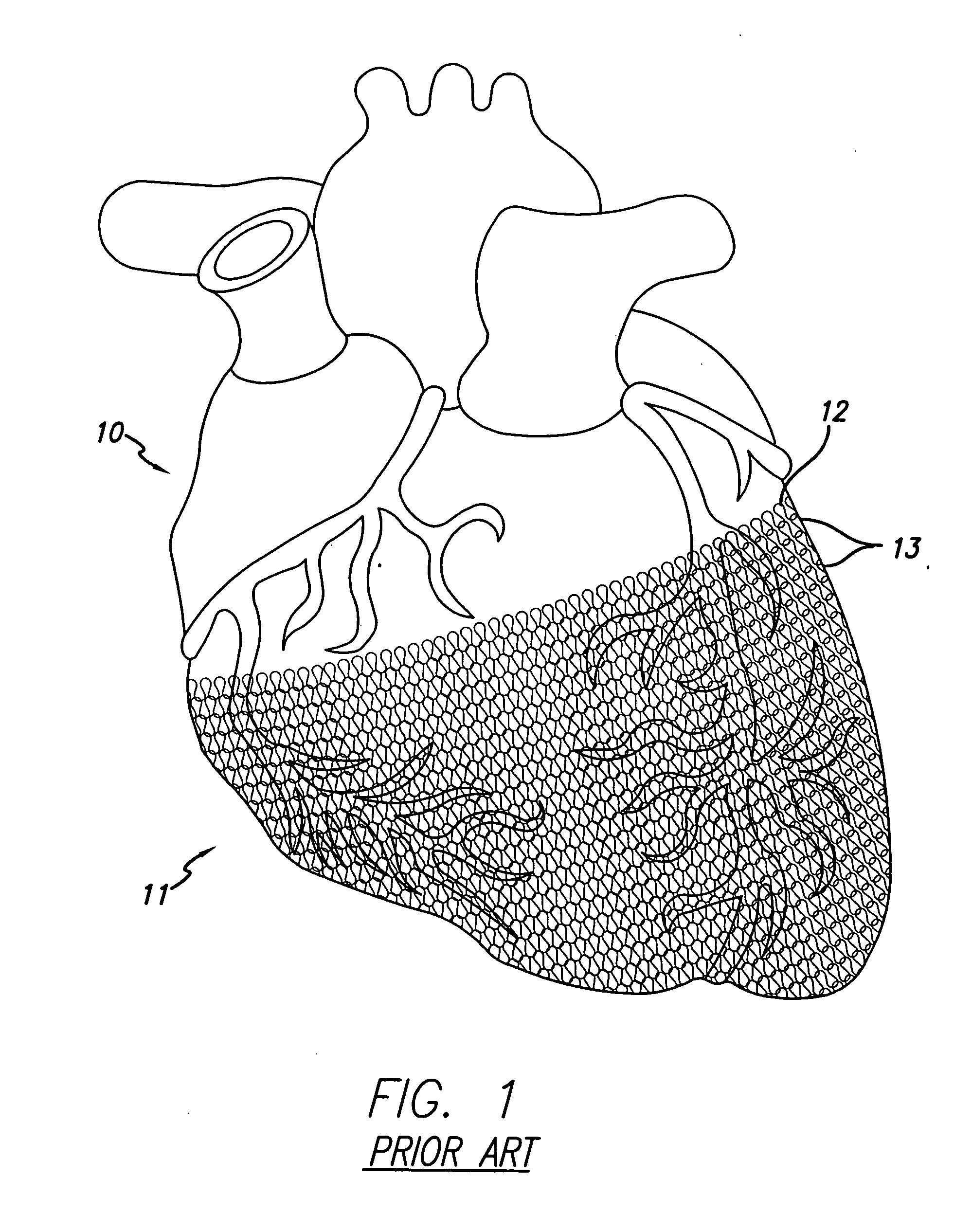
[0056] The present invention relates to a method and apparatus for treating heart failure. As discussed in Applicants' co-owned and co-assigned patent entitled “Expandable Cardiac Harness For Treating Congestive Heart Failure”, U.S. Pat. No. 6,702,752, which was filed on Aug. 8, 2000, the entirety of which is hereby expressly incorporated by reference herein, it is anticipated that remodeling of a diseased heart can be resisted or even reversed by alleviating the wall stresses in such a heart. The present disclosure discusses certain embodiments and methods for supporting the cardiac wall. Additional embodiments and aspects are also discussed in Applicants' co-pending applications entitled “Heart Failure Treatment Device and Method,” Ser. No. 10 / 287,723, filed Oct. 31, 2002, “Method and Apparatus for Supporting a Heart,” Ser. No. 10 / 338,934, filed Jan. 7, 2003, “Cardiac Harness,” Ser. No. 10 / 656,722, filed Sep. 5, 2003, and Applicant's co-owned and co-assigned patent entitled “Devic...


PUM


Abstract

A cardiac harness is configured to fit at least a portion of a patient's heart and at least a portion of the cardiac harness includes a radiopaque coating. The radiopaque coating is formed from a polymer loaded with a radiopaque material such as barium sulfate. The radiopaque material also includes a radiopaque band or a radiopaque coating formed by sputter coating or the like. The radiopaque material is visible under fluoroscopy, MRI, or echocardiography.

Description

[0001] This is a continuation-in-part of U.S. Ser. No. 10 / 811,245 filed Mar. 25, 2004, which depends for priority upon U.S. Provisional Patent Application No. 60 / 458,991, filed Mar. 28, 2003, the entirety of each of which is herein incorporated by reference.BACKGROUND OF THE INVENTION [0002] The present invention relates to a device for treating heart failure. More specifically, the invention relates to a cardiac harness configured to be fit around at least a portion of a patient's heart. The cardiac harness is configured to be radiopaque for enhanced visualization under fluoroscopy. The cardiac harness includes an arrangement that provides no electrical continuity circumferentially about the harness, and therefore allows an electric current to pass through the heart unimpeded. In a situation where a defibrillating electrode positioned inside the right ventricle of a patient is connected to an implantable cardiac defibrillator (“ICD”), the arrangement of the cardiac harness will all...

Claims


Application Information

Patent Timeline
IPC IPC(8): A61F2/00A61N1/368
CPCA61F2/2481A61N1/368A61F2002/2484
Inventor MEYER, STEVELAU, LILIP
Owner PARACOR MEDICAL
Learn More