Embolic protection device

a protection device and embolism technology, applied in the field of embolism protection devices, can solve the problems of neurological impairment, patient experiencing a loss of function, brain impairment either temporarily or permanently, etc., and achieve the effect of facilitating the maintenance of the filter position

Inactive Publication Date: 2005-12-22
SALVIAC
View PDF99 Cites 45 Cited by
  • Summary
  • Abstract
  • Description
  • Claims
  • Application Information

AI Technical Summary

Benefits of technology

[0016] Advantageously, the inlet openings in the filter are closed before the fitter is collapsed ensuring retention of all embolic material within the filter element.
[0078] In one embodiment of the invention, the filter element incorporates proximal tapering such that it may be pulled proximally into a sheath for removal in order that such pulling action will effectively reduce the diameter of the filter and assist retrieval.

Problems solved by technology

The brain will be impaired either temporarily or permanently, with the patient experiencing a loss of function such as sight, speech or control of limbs.
The nature of the plaque varies considerably, but in a significant number of cases pieces of the plaque can break away and flow distally and block blood flow to specific areas of the brain and cause neurological impairment.
A number of reasons may exist such that the patients could not tolerate surgical intervention.
The action of these devices as with surgery can dislodge embolic material which will flow with the arterial blood and if large enough, eventually block a blood vessel and cause a stroke.
However, as the filter collapses, the captured embolic material tends to be squeezed outwardly towards an open end of the filter and pieces of embolic material may escape from the filter with potentially catastrophic results.

Method used


Image

  • Embolic protection device
  • Embolic protection device
  • Embolic protection device

Examples


Embodiment Construction

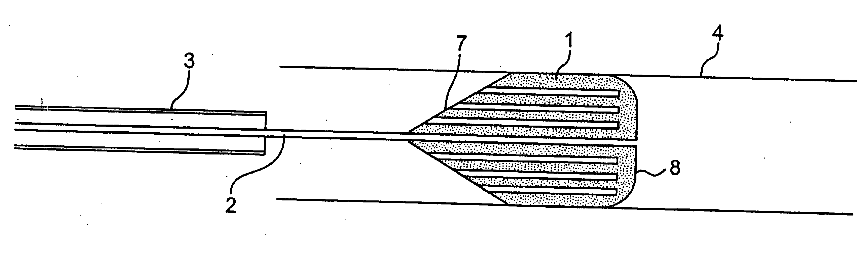
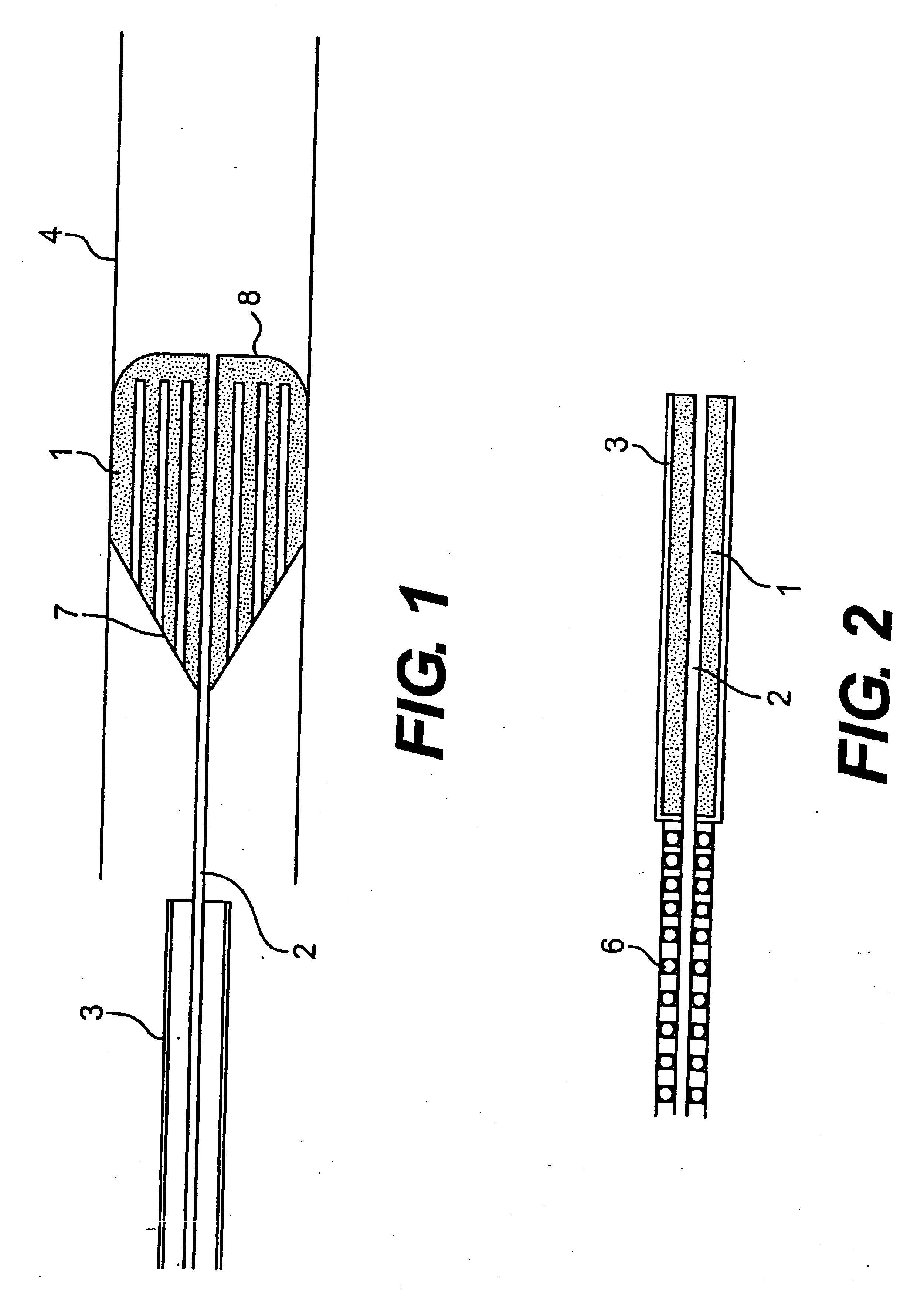
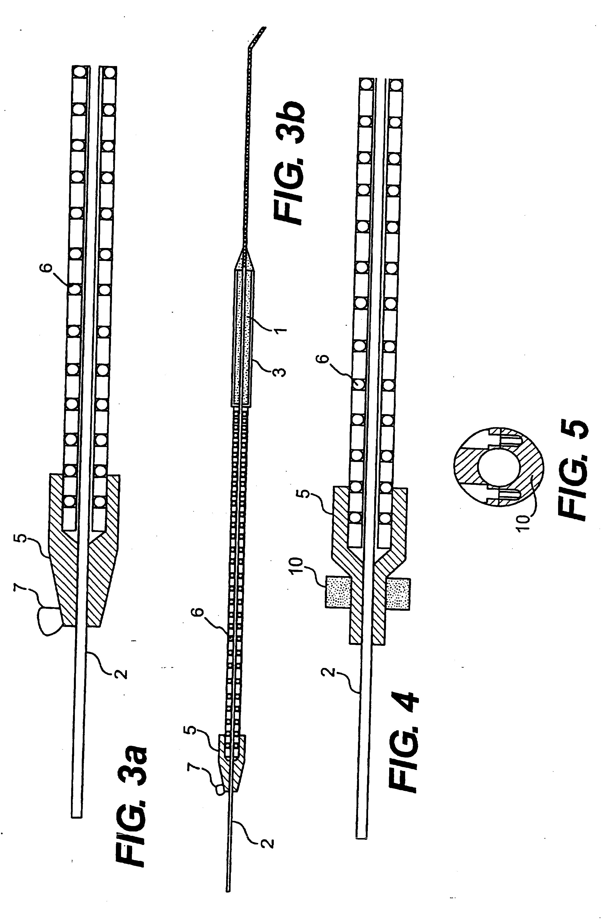
[0130] Referring to the drawings there are illustrated various embolic protection devices according to the invention. The devices, in general, comprise a filter element for temporary placing in a desired position during a surgical or interventional procedure typically using a guidewire and catheter. The filter element provides a pathway for blood and has means for capturing and retaining undesired embolic material released during the surgical procedure. The filter element containing the retained embolic material is removed when the interventional procedure is completed. In this way the patient is protected against the risk of stroke or other complications caused by the release of undesired embolic material during the procedure.

[0131] In one embodiment of the device it will be used in an over the wire transcatheter configuration. The clinician will cross the lesion with a steerable guidewire. The cerebral protection device will then be threaded over the guidewire and will be placed ...


PUM


Abstract

An embolic protection device has a collapsible filter element (105) mounted on a carrier such as a guidewire (101). The filter element (105) collapses into the outer end of a catheter (118) for deployment and retrieval through a vascular system of a patient. The filter element (105) has a collapsible filter body with a proximal inlet end and a distal outlet end. The proximal inlet end has inlet openings sized to allow blood and embolic material enter the filter body. The outlet end has outlet openings which allow through passage of blood but retain embolic material within the filter body. After use, the catheter (118) is movable along the guidewire (101) to engage the proximal end of the filter element and close the inlet openings before sliding over the filter element from the proximal end to the distal end to progressively collapse the filter body on the guidewire (101) for retrieval. The filter element (105) may conveniently be mounted on a tubular sleeve (104) which is slidable and rotatable on the guidewire (101) between spaced-apart stops (106, 120) on the guidewire (101) which allows some manipulation of the guidewire independently of the filter when the filter is in use.

Description

[0001] The invention relates to an embolic protection device. [0002] The term “STROKE” is used to describe a medical event whereby blood supply to the brain or specific areas of the brain is restricted or blocked to the extent that the supply is inadequate to provide the required flow of oxygenated blood to maintain function. The brain will be impaired either temporarily or permanently, with the patient experiencing a loss of function such as sight, speech or control of limbs. There are two distinct types of stroke, hemorrhagic and embolic. This invention addresses embolic stroke. [0003] Medical literature describes carotid artery disease as a significant source of embolic material. Typically, an atherosclerotic plaque builds up in the carotid arteries. The nature of the plaque varies considerably, but in a significant number of cases pieces of the plaque can break away and flow distally and block blood flow to specific areas of the brain and cause neurological impairment. Treatment...

Claims


Application Information

Patent Timeline
Patent Type & Authority Applications(United States)
IPC IPC(8): A61B17/00A61B17/22A61F2/01A61F2/06A61M25/00A61M25/09A61M29/00A61M31/00
CPCA61B2017/22051A61B2017/22067A61F2/01A61F2/013A61F2002/011A61F2002/015A61F2230/0097A61F2002/018A61F2230/0006A61F2230/0067A61F2230/0069A61F2230/0093A61F2002/016A61F2/011A61F2/0108
Inventor GILSON, PAULBRADY, EAMONMAHER, PADRAIGVALE, DAVIDTAYLOR, CHARLES
Owner SALVIAC
Why Eureka
Try Eureka