Reactive sensor modules using pade' approximant based compensation and providing module-sourced excitation

a sensor module and approximant-based compensation technology, applied in the field of electronic systems, can solve the problems of presenting unique requirements and limitations, affecting the accuracy of the measurement of the under-measured physical parameter, and affecting the accuracy of the measurement. , to achieve the effect of high accuracy, low cost and simple and low cos

Active Publication Date: 2005-12-22
SEMICON COMPONENTS IND LLC +1
View PDF1 Cites 259 Cited by
  • Summary
  • Abstract
  • Description
  • Claims
  • Application Information

AI Technical Summary

Benefits of technology

[0061] One class of embodiments of the invention comprises a sensor-module housing where the housing contains at least part of a reactive sensor (e.g., the coil portion of a variable reluctance inductor), a monolithic integrated circuit and a timing reference (e.g., an oscillator crystal). The integrated circuit includes a voltage reference, a waveform generator for generating a sensor exciting signal that is synthesized from use of the timing reference and the voltage reference, a detector for detecting the response of the sensor to the combination of the exciting signal and the under-measure physical parameter, a temperature compensating unit, and a Pade' Approximant based, nonlinearity compensating unit. The temperature compensating unit and the Pade' Approximant nonlinearity compensating unit are tuned by use of digitally programmed coefficients. The coefficients calibrate the output signal of the sensor module as well as compensating for nonlinearity and temperature sensitivity in both the sensor and the signal path between the sensor and the sensor-module output signal. A highly accurate measurement of the under-measure physical parameter is made possible even though each of the sensor and compensating circuitry may be relatively simple, compact, and low in cost.
[0062] It may be seen from the above example that the present invention provides a solution wherein a relatively simple and low-cost reactive sensor (e.g., a simple coil and movable core member) can be used in combination with programmably-tuned compensation circuitry to thereby provide a combination that is accurate, low in cost and compact. Although the sensor may be relatively inaccurate and prone to temperature drift when characterized alone, the combination of the sensor and compensating circuitry can be made relatively accurate and insensitive to temperature changes. The invention provides nonlinearity and temperature compensating methods and corresponding structures that can be used with reactive sensors that require AC excitation sources as well as individualized output correction. Structures in accordance with the invention can be made compact, with relatively low power consumption and yet they can be made highly accurate because they are programmably adjustable to accommodate the idiosyncrasies of individual sensors. Structures in accordance with the invention can be made flexible so as to be used in a wide range of applications while allowing for low cost mass production. Methods and structures disclosed herein allow for sensor excitation and calibration to take place as an integral part of nonlinearity compensation, where both functions may be implemented by the same circuit. Embodiments in accordance with the invention may be implemented as monolithic integrated circuits which use mostly analog techniques for providing signal conditioning that is free of digitization problems (e.g., quantization error and / or sample time hold up).
[0071] A nonlinearity compensation circuit in accordance with the invention can be placed anywhere in the analog signal path of the sensor module. The compensation function can include compensation for the compensator's internal nonlinearities and for nonlinearities of other circuits in the reporting path. Because the compensation does not necessitate adjustment of a sensor excitation signal (as might for example, certain resistance bridge circuits), the sensor excitation signal may be kept constant or it may be made ratiometric to the supply voltage. This allows for a simpler design and can help to ensure that the sensor excitation voltage or current will be within an optimal range as may be required by the unique circumstances of each sensor and its use. As an additional benefit, the nonlinearity compensation circuit can also provide sensor calibration, thus further reducing overall complexity and cost. When compared to the predominantly digital methods for nonlinearity compensation, where large lookup tables, microprocessors and / or the like are employed, the embodiments in accordance with the present invention enable much simpler and smaller circuits that can be built at significantly lower costs.

Problems solved by technology

However, in various modern application areas such as automotive, the size, weight, cost, power consumption, and interface-ability of sensors can become very important issues, especially when sensors are to be embedded ubiquitously about a vehicle or other structure and coupled to a serial data channel in order to allow the structure to operate more smartly.
Providing appropriate support for such AC-excited sensors can be a problem.
Many sensing elements, including inductive and / or capacitive ones, present unique requirements and limitations that need to be somehow circumvented or compensated for or supported by external means.
Often, the electric or other output signal that is generated by the inductive and / or capacitive sensor in response to a given physical attribute (e.g., force, displacement, velocity, acceleration, temperature or any other physical parameter that can be detected and / or measured) is comparatively weak, distorted, or simply not adequate to interface directly with the electronic or other control system that is to rely on the sensor output signal.
The non-ideal response functions may be plagued by variation of response over different temperature ranges and / or by nonlinear response to linear change in the physical parameter being measured.
Part of the problem is that the AC excitation signal can alter sensor behavior.
Adjusting each potentiometer in a mass production environment is tedious, expensive and error-prone work.
Even when done properly in the factory, it does not guarantee that phase matching will exist over all the sensor's temperature operating range in the field.
The computational circuitry results in a fairly complex product that is sold at a relatively high cost (see Ford et al).
It cannot be used with mechanically simpler 4-wire LVDTs.
All these reasons severely limit the scope of application for this second approach.
Although improving on different aspects of performance, these DSP solutions of the third approach are complex and expensive.
They cannot be used in cost-sensitive LVDT applications.
Aside from the above three approaches, which are dedicated to LVDTs or RVDTs, it is believed that there are no commercially standard monolithic solutions for providing signal conditioning for other types of inductive and capacitive sensors (those that are not LVDTs).
Therefore, users of the vast majority of reactive sensors are left to developing their own dedicated signal conditioning circuits, if they are going to have signal conditioning at all, where the dedicated signal conditioning circuits have a relatively large number of components and tend to be costly, bulky and consume more power.
They do not simultaneously attempt to provide calibration for the peculiarities of each individual sensing element or to compensate for the sensor's temperature variations.
This tends to increase overall module size, cost and power consumption.
In particular, it is believed that the rational functions provided by the Padé Approximant approach generally provide a better fit for modeling real world phenomenon than do the more commonly used Taylor expansions, where the latter disadvantageously call for a larger number of terms and associated coefficients in order to define an approximation to a desired degree of accuracy and precision.

Method used


Image

  • Reactive sensor modules using pade' approximant based compensation and providing module-sourced excitation
  • Reactive sensor modules using pade' approximant based compensation and providing module-sourced excitation
  • Reactive sensor modules using pade' approximant based compensation and providing module-sourced excitation

Examples


Embodiment Construction

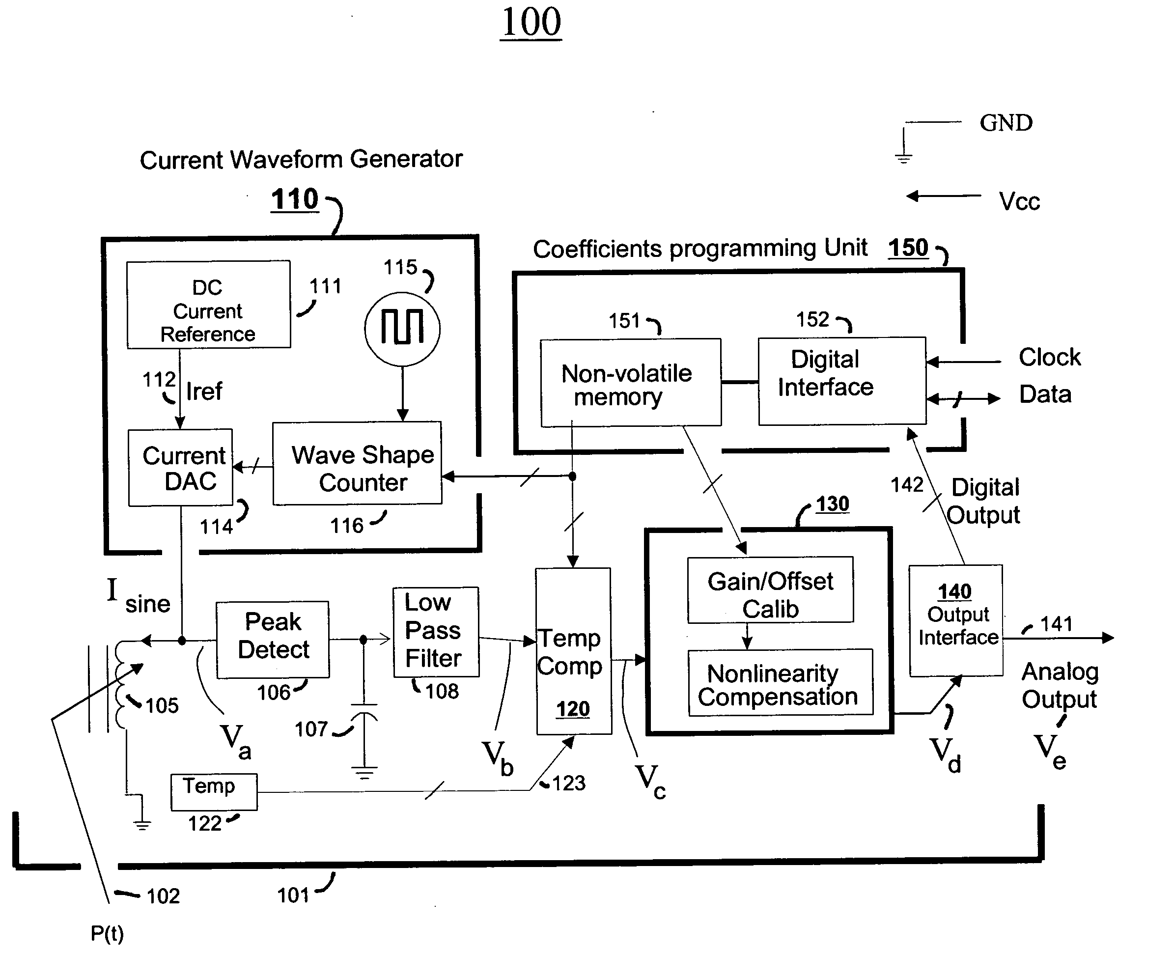
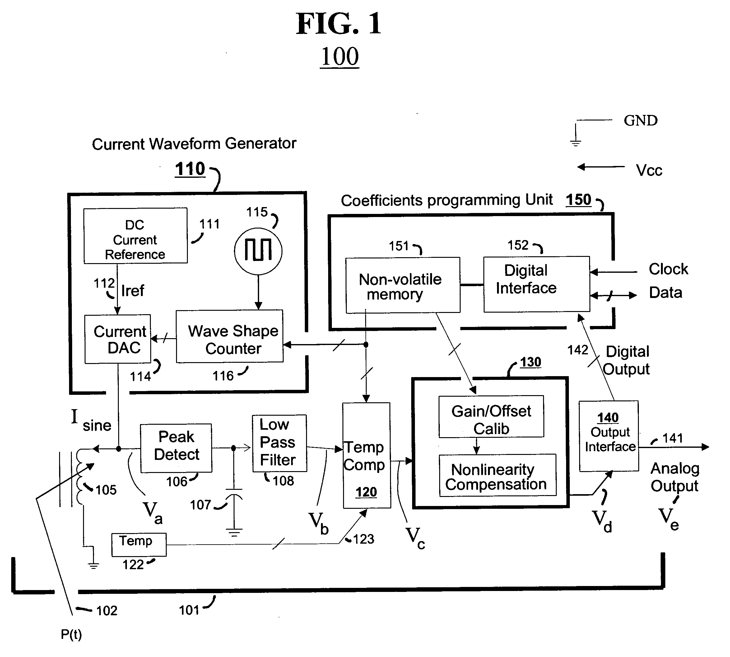
[0087] The following description is illustrative only and not limiting. Referring to FIG. 1, a block diagram is provided of a sensor module 100 including a variable reluctance sensor 105. In one embodiment, the module comprises a printed circuit board (not shown) to which are mounted a sensor coil, a monolithic integrated circuit (IC, not separately shown) and an oscillator crystal. The printed circuit board is surrounded by a protective housing 101 (partially shown) such as a hermetically sealed, non-magnetic metal casing (e.g., aluminum). The coil is positioned near a wall of the protective housing 101 so as to interact with an external and movable, magnetic core member 102. An external physical parameter, P(t), such as a position of the movable, magnetic core member 102, alters the reluctance of the so-formed sensor 105.

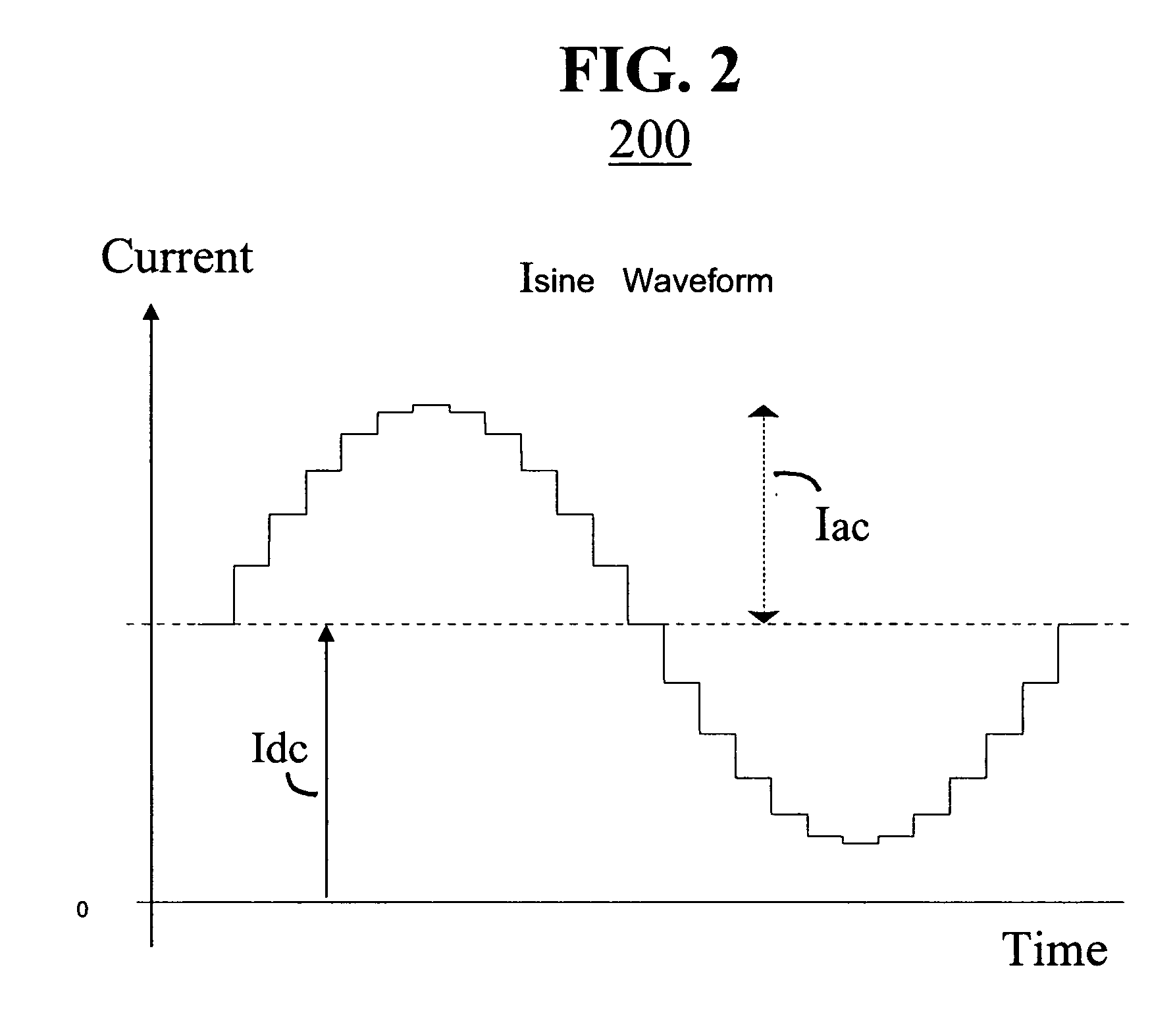
[0088] A current generator 110 is provided within the IC for driving a periodic current signal, Isine through the variable reluctance sensor 105, where Isine is d...


PUM


Abstract

Reactive sensors typically exhibit nonlinear response to the combination of an excitational signal (e.g., sinusoidally oscillating signal) and a physical parameter under measure (e.g., position of magnetic core member). Such sensors are typically sensitive to temperature variation. Systems and methods are disclosed for compensating for the nonlinear and / or temperature dependant behavior of reactive sensors and for calibrating the post-compensation output signals relative to known samples of the physical parameter under measure (e.g., position). One class of embodiments comprises a housing containing at least part of a reactive sensor, a monolithic integrated circuit and a timing reference (e.g., an oscillator crystal). The integrated circuit includes a waveform generator for generating a sensor exciting signal, a detector for detecting the response of the sensor to the combination of the exciting signal and the under-measure physical parameter, a temperature compensating unit and a Pade' Approximant based, nonlinearity compensating unit. The temperature compensating unit and the Pade' Approximant nonlinearity compensating unit are tuned by use of digitally programmed coefficients. The coefficients calibrate the final output as well as compensating for nonlinearity and temperature sensitivity. A highly accurate measurement of the under-measure physical parameter is made possible even though each of the sensor and compensating circuitry may be relatively simple, compact, and low in cost.

Description

FIELD OF DISCLOSURE [0001] The present invention relates generally to electronic systems which compensate for analog transducer nonlinearities and / or temperature drift. [0002] More specifically, the invention relates to integrated sensor modules where a transducer is packaged together with compensating means such as electronic compensating circuitry and where the transducer includes a reactive component such as an inductor or a capacitor. 2a. CROSS REFERENCE TO PATENTS [0003] The disclosures of the following U.S. patents are incorporated herein by reference: [0004] (A) U.S. Pat. No. 6,198,296, issued Mar. 6, 2001 to Ivanov and entitled “Bridge sensor linearization circuit and method”; [0005] (B) U.S. Pat. No. 5,902,925, issued May 11, 1999 to Crispie et al. and entitled “System and method for high accuracy calibration of a sensor for offset and sensitivity variation with temperature”; [0006] (C) U.S. Pat. No. 5,848,383, issued Dec. 8, 1998 to Yunus and entitled “System and method fo...

Claims


Application Information

Patent Timeline
Patent Type & Authority Applications(United States)
IPC IPC(8): G01C19/00G01C25/00G01D3/02G01D18/00G01F25/00G06F19/00
CPCG01C25/00G01D18/008G01D3/022G01D3/0365
Inventor LARAIA, JOSE MARCOSNIWA, MASAHISAMOEHRKE, ROBERT P.TAVEIRA, JOSE G.
Owner SEMICON COMPONENTS IND LLC
Why Eureka
Try Eureka