Thermo siphon chiller refrigerator for use in cold district

a chiller refrigerator and thermosiphon technology, applied in the direction of cooling fluid circulation, domestic cooling apparatus, lighting and heating apparatus, etc., can solve the problems of low investment efficiency, low utilization factor of equipment, and high equipment cost, and achieve smooth compressor operation and eliminate the effect of flow resistan

Inactive Publication Date: 2005-12-29
MAYEKAWA MFG CO LTD
View PDF10 Cites 28 Cited by
  • Summary
  • Abstract
  • Description
  • Claims
  • Application Information

AI Technical Summary

Benefits of technology

[0027] The above invention is constituted such that, a compressor is joined to the conventional natural refrigerant circulation refrigerating system comprising an outdoor heat exchanger functioning as a condenser, an indoor heat exchanger functioning as an evaporator and being located in a position lower than that of the outdoor heat exchanger, and refrigerant piping, and the compressor is connected to the outdoor heat exchanger and indoor heat exchanger to make it possible to perform vapor compression cycle by switching the path of refrigerant flow. When outside air temperature is higher than a predetermined temperature, the refrigerant-flow path is switched to perform a vapor compression refrigerating cycle.

Problems solved by technology

When considering the case the proposal disclosed in Japanese Laid-Open Patent Application No.10-300128 is used in a cold district, the second and third embodiments can accommodate enough to the environment, however, two sets of indoor heat exchangers, outdoor heat exchangers, and refrigerant pipe lines are necessary to be provided, and there is a problem of the high cost of equipment.
Further, one of the two systems is the equipment for backing-up when outside temperature is high, so the utilization factor of the equipment is low and accordingly the investment efficiency is low.

Method used


Image

  • Thermo siphon chiller refrigerator for use in cold district
  • Thermo siphon chiller refrigerator for use in cold district
  • Thermo siphon chiller refrigerator for use in cold district

Examples


Embodiment Construction

[0040] A preferred embodiment of the present invention will now be detailed with reference to the accompanying drawings. It is intended, however, that unless particularly specified, dimensions, materials, relative positions and so forth of the constituent parts in the embodiments shall be interpreted as illustrative only not as limitative of the scope of the present invention.

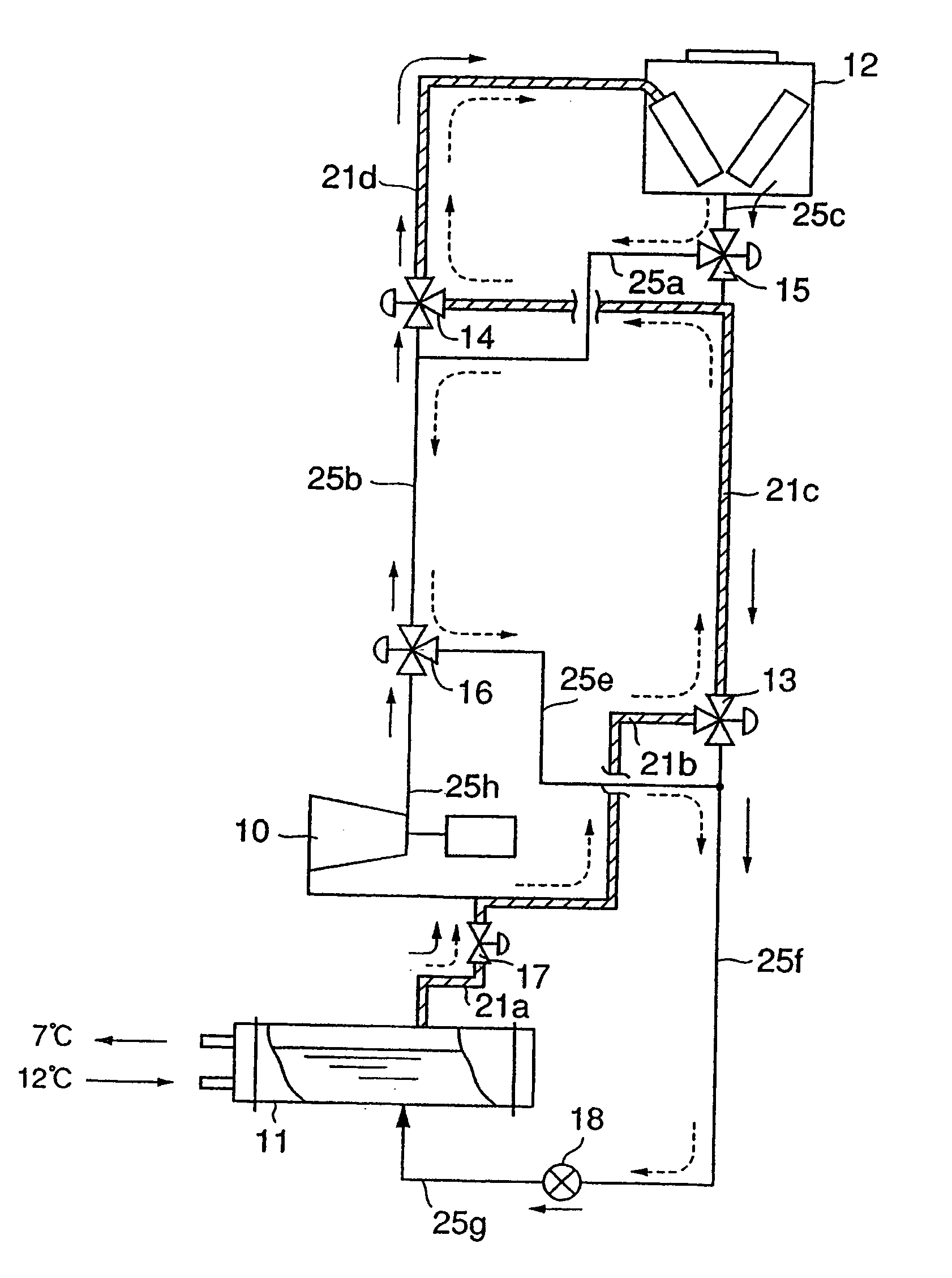
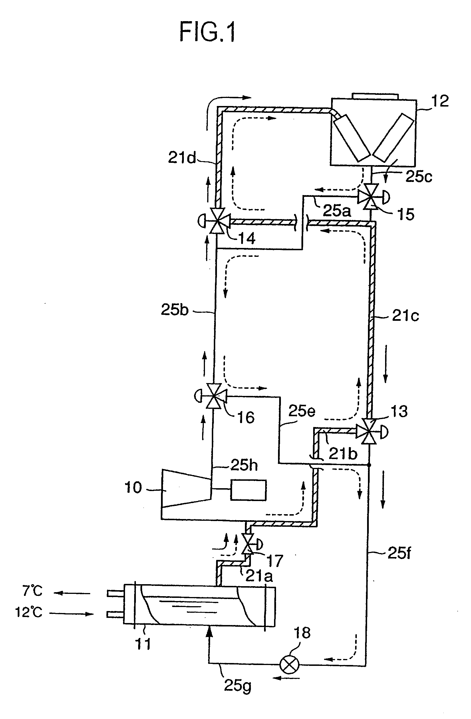
[0041]FIG. 1 is an illustration showing the schematic configuration of the thermo-siphon chiller refrigerator for use in cold districts according to the present invention.

[0042] The thermo-siphon chiller refrigerator for use in cold districts of the present invention constitutes, as shown in FIG. 1, a natural refrigerant-circulation refrigerating cycle and a forced refrigerant-circulation refrigerating cycle (vapor compression refrigerating cycle), which can supply cold air of 7° C. when atmospheric temperature rises over a predetermined value in summer by the operation of the vapor compression refrigerating ...


PUM


Abstract

In order to provide a thermo-siphon chiller refrigerator for use in cold districts which performs natural refrigerant-circulation refrigerating cycle and also can perform a forced refrigerant-circulation refrigerating cycle when outside air temperature is high by using an indoor heat exchanger, an outdoor heat exchanger, and a compressor, and combining them with refrigerant piping, the thermo-siphon chiller refrigerator for use in cold districts of the invention has a compressor (10) additionally installed to a natural refrigerant-circulation refrigerating system comprising an outdoor heat exchanger (12), an indoor heat exchanger (11) located at a position lower than that of the outer heat exchanger (12), and an expansion valve (18). When the refrigerating capacity of the natural refrigerant circulation refrigerating system is not sufficient, the additional compressor (10) is operated to perform a forced refrigerant-circulation cycle i.e. a vapor compression refrigerating cycle.

Description

FIELD OF THE INVENTION [0001] The present invention relates to an energy-saving thermo-siphon chiller refrigerator which can perform a vapor compression refrigerating cycle(forced circulation cycle of refrigerant) in summer as a backup refrigerating cycle of the thermo-siphon chilling cycle(natural circulation cycle of refrigerant). TECHNICAL BACKGROUND [0002] Large scale buildings in cold districts may need cooling even in the condition the atmosphere is cold in winter, particularly in a data center, etc. where a large amount of heat is generated by communication service equipment. Therefore, generally, room coolers are operated there even in winter. [0003] The air conditioning system generally used for air conditioning of a building is composed of, as shown in FIG.2, an outdoor heat exchanger 102 functioning as a condenser, a receiver 108, an indoor heat exchanger 101 functioning as an evaporator, a compressor 110, and an expansion valve 104. The system performs a vapor compressio...

Claims


Application Information

Patent Timeline
Patent Type & Authority Applications(United States)
IPC IPC(8): F25B23/00F25B25/00F25B1/00F25B41/00F25B41/04
CPCF25B23/006F25B25/00F25B41/00F25B2339/024F25B2400/0401F25B2500/01F25B2600/111Y02B30/70F25B41/22
Inventor TAMURA, YOSHIHISAKOYATSU, MASATAKAMACHIDA, AKITO
Owner MAYEKAWA MFG CO LTD
Why Eureka
Try Eureka