Wear gauge and method of use

a technology of wear gauge and wear pattern, which is applied in the direction of optical radiation measurement, instruments, manufacturing tools, etc., can solve the problems of not measuring wear rate or identifying specific wear regions on the head, and not providing a good measure of the microscopic wear profil

Inactive Publication Date: 2005-12-29
GLOBALFOUNDRIES INC
View PDF5 Cites 34 Cited by
  • Summary
  • Abstract
  • Description
  • Claims
  • Application Information

AI Technical Summary

Problems solved by technology

The contact at the head/medium interface results in wear which is a major concern affecting performance and lifetime of both head and medium.
In magnetic tape and disk recording systems, considerable effort has been made to determine the wear resistance of magnetic head materials in contact with the recording media.
As recording density increases, knowledge of the head wear characteristics becomes of increased importanc

Method used


Image

  • Wear gauge and method of use
  • Wear gauge and method of use
  • Wear gauge and method of use

Examples


Embodiment Construction

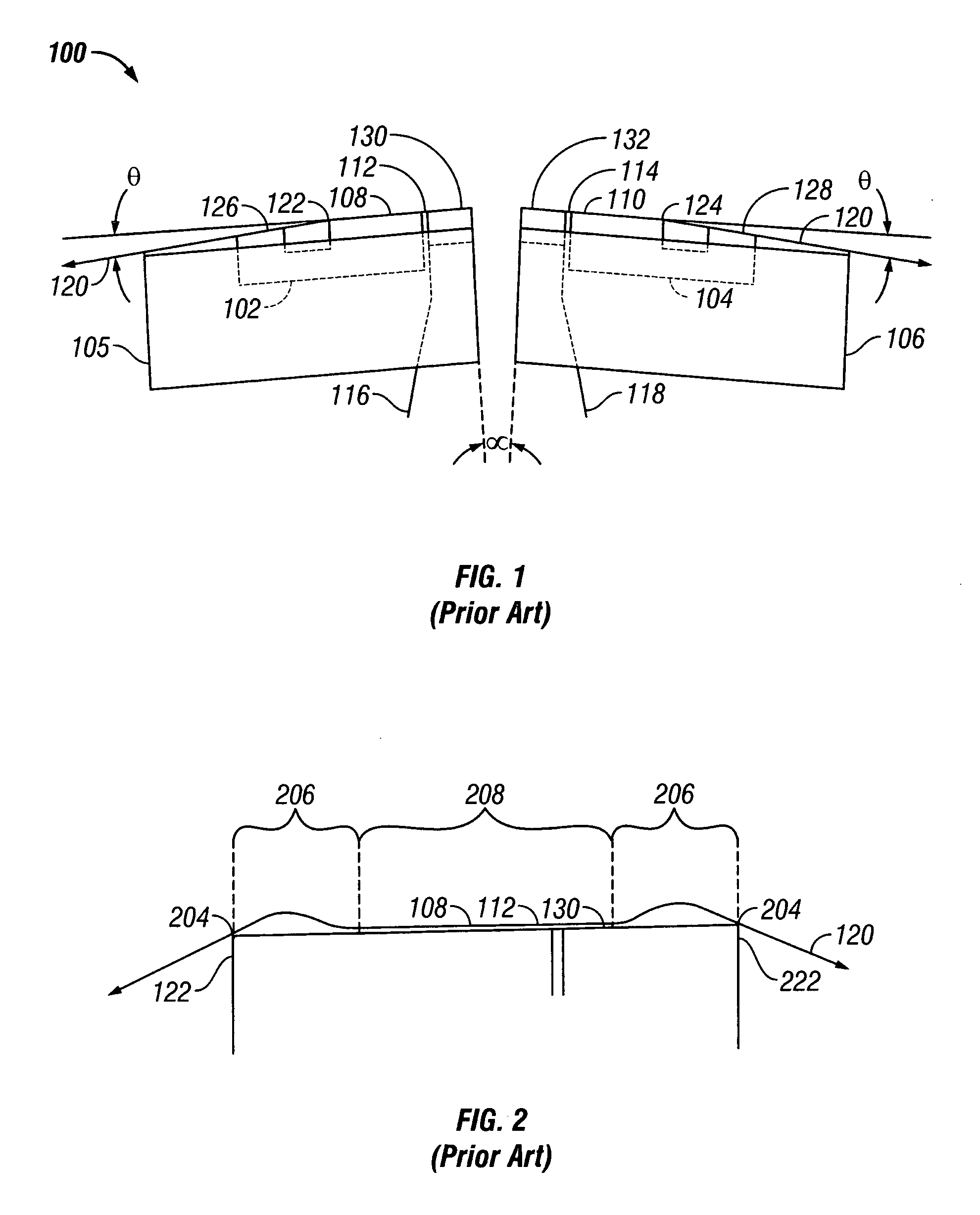
[0022]FIG. 1 illustrates a prior art bi-directional read-while-write flat contour tape recording head 100. Rowbar substrates 102 and 104 of a wear resistant material, such as the substrate ceramic typically used in magnetic disk drive heads, are mounted in carriers 105 and 106 fixed at a small angle α with respect to each other. The ceramic rowbar substrates 102 and 104 are provided with flat transducing surfaces 108 and 110 and a row of transducers at the surfaces of gaps 112 and 114. Electrical connection cables 116 and 118 connect the transducers to the read / write channel of the associated tape drive. To control the overwrap angle θ of the tape 120 at edges 122 and 124, outriggers 126 and 128 lapped at the desired wrap angle are provided. The wrap angle going onto the flat transducing surface is usually between ⅛ degree and 4.5 degrees. The rows of transducers are protected by closures 130 and 132 made of the same or similar ceramic as the rowbar substrates 102 and 104.

[0023]FIG...


PUM

PropertyMeasurementUnit
Thicknessaaaaaaaaaa
Angleaaaaaaaaaa
Lengthaaaaaaaaaa

Abstract

A wear gauge is provided for simulating the wear of a magnetic recording component at its interface with a magnetic storage medium comprising a wear gauge block having a wear surface that substantially approximates the geometrical dimensions and contour of the working surface of the magnetic recording component, wherein the wear surface has a coating of transparent material. A test method comprises mounting the wear gauge in a test fixture, positioning a tape and adjusting the overwrap angle at edges of the wear surface, choosing the desired tape tension, speed and runtime, and running the tape, preferably unidirectionally, in operational contact with the wear surface for the desired runtime. The wear surface is inspected under white light illumination to observe and record locations of interferometric color changes on the wear surface. The color changes are correlated to thickness changes of the transparent coating on the wear surface.

Description

BACKGROUND OF THE INVENTION [0001] 1. Field of the Invention [0002] This invention relates to wear gauges, and more particularly, to a wear gauge for measuring tape head wear in a magnetic tape recording system and to a method of measuring tape head contact pressure distribution and wear. [0003] 2. Description of the Related Art [0004] In magnetic recording systems, the mechanical interaction of the magnetic head and the recording medium is an important factor determining the performance and reliability of the system. Ideally, the head is in contact or near contact with the moving recording medium to optimize read / write processes. The contact at the head / medium interface results in wear which is a major concern affecting performance and lifetime of both head and medium. [0005] In magnetic tape and disk recording systems, considerable effort has been made to determine the wear resistance of magnetic head materials in contact with the recording media. As recording density increases, k...

Claims


Application Information

Patent Timeline
IPC IPC(8): G01B11/06G01N3/02G01N3/06G01N3/56G01N3/62G01N21/84G11B5/41
CPCG01N3/56G01N2203/0246Y10T29/49986G11B5/41G01N2203/0664
Inventor BISKEBORN, ROBERT GLENNLIANG, JASON
Owner GLOBALFOUNDRIES INC
Why Eureka
Try Eureka