
Production system for corrugated carboard sheet

a production system and corrugated carboard technology, applied in the direction of process and machine control, mechanical control devices, instruments, etc., can solve the problems of inferior gluing, travel-direction warp, travel-direction warp, etc., and achieve the effect of accurate correction and eas

Inactive Publication Date: 2005-12-29
MITSUBISHI HEAVY IND PRINTING & PACKAGING MACHINERY
View PDF11 Cites 24 Cited by
  • Summary
  • Abstract
  • Description
  • Claims
  • Application Information

AI Technical Summary

Benefits of technology

[0029] It is the first object of the present invention is to provide a system for correcting warp of a corrugated board sheet in which warp of a corrugated board sheet is accurately corrected with ease without depending on the experience of an operator and know-how.

Problems solved by technology

At that time, an inappropriate level of heat or amount of glue causes defects in a resultant corrugated board sheet, e.g., width-direction upward or downward warp (hereinafter simply called width-direction warp) or inferior gluing.
For example, an excessive moisture content of a bottom liner causes a convex surface toward a top liner when being dried; and an excessive moisture content of the top liner causes a convex surface toward the bottom liner when being dried.
Further, during the fabrication process, if a transfer-direction (hereinafter also called travel-direction) tension of a top liner or a single-face sheet is out of the appropriate range so that there is a significant difference in travel-direction tension between a top liner and a single-face web, the resultant corrugated board sheet has a defect such as travel-direction upward / downward warp (hereinafter simply called travel-direction warp) or inferior gluing.
However, such an adjustment manner depending on experience or know-how may lead to inconsistency in quality of resultant corrugated board sheets depending on different operators's skill levels.
Additionally, the same operator may repeat the adjustment over and over and may make errors in the adjustment operation leading to difficulties in obtaining constant product quality.
Further, since there are a great number of control factors to be adjusted and adjustment variables of each control factor are determined considering current values, the adjustment operation is complex and time-consuming.
During an exceptional production state in which a top liner and a bottom liner have the same base board composition and have different moisture contents or base boards of the same type are different in moisture content, even if each control factor is automatically adjusted in the above system, temperature of a web does not reach a predetermined appropriate temperature and, as a result, the resultant corrugated board sheets may have width-direction warp.
Therefore, adjustment for only the above selected control factors takes a long time to correct warp of large extent and, in extreme cases, there is a possibility that travel-direction warp cannot be corrected.
The above moisture-content unevenness and temperature unevenness may sometimes cause a resultant corrugated board sheet to have width-direction S-shape warp.
However, this technique largely affects tension of a web, e.g., variation in tension distribution in the width direction of the web, resulting in warp.
There is a possibility that the S-shape warp cannot be satisfactorily inhibited and that warp of another type may be generated on a resultant corrugated board sheet.
A visual operator check, however, cannot quantitatively grasp a warp amount of a corrugated board sheet, so it is difficult to accurately correct the warp of the corrugated board sheet as a result of such a visual check.
There has not been developed a technique to quantitatively detect an amount of travel-direction warp or twist warp.
The above counting roll, however, may be not able to obtain an exact number of fabricated corrugated board sheets because of slipping between the counting roll and transferred double-face web.
Further, corrugated board sheets having large warp or inferior gluing may sometimes be removed as being defective during transfer.

Method used


Image

  • Production system for corrugated carboard sheet
  • Production system for corrugated carboard sheet
  • Production system for corrugated carboard sheet

Examples


tenth embodiment

(B-2) Tenth Embodiment

[0345]FIG. 21 shows a system for fabricating a corrugated board sheet according to the tenth embodiment of the present invention.

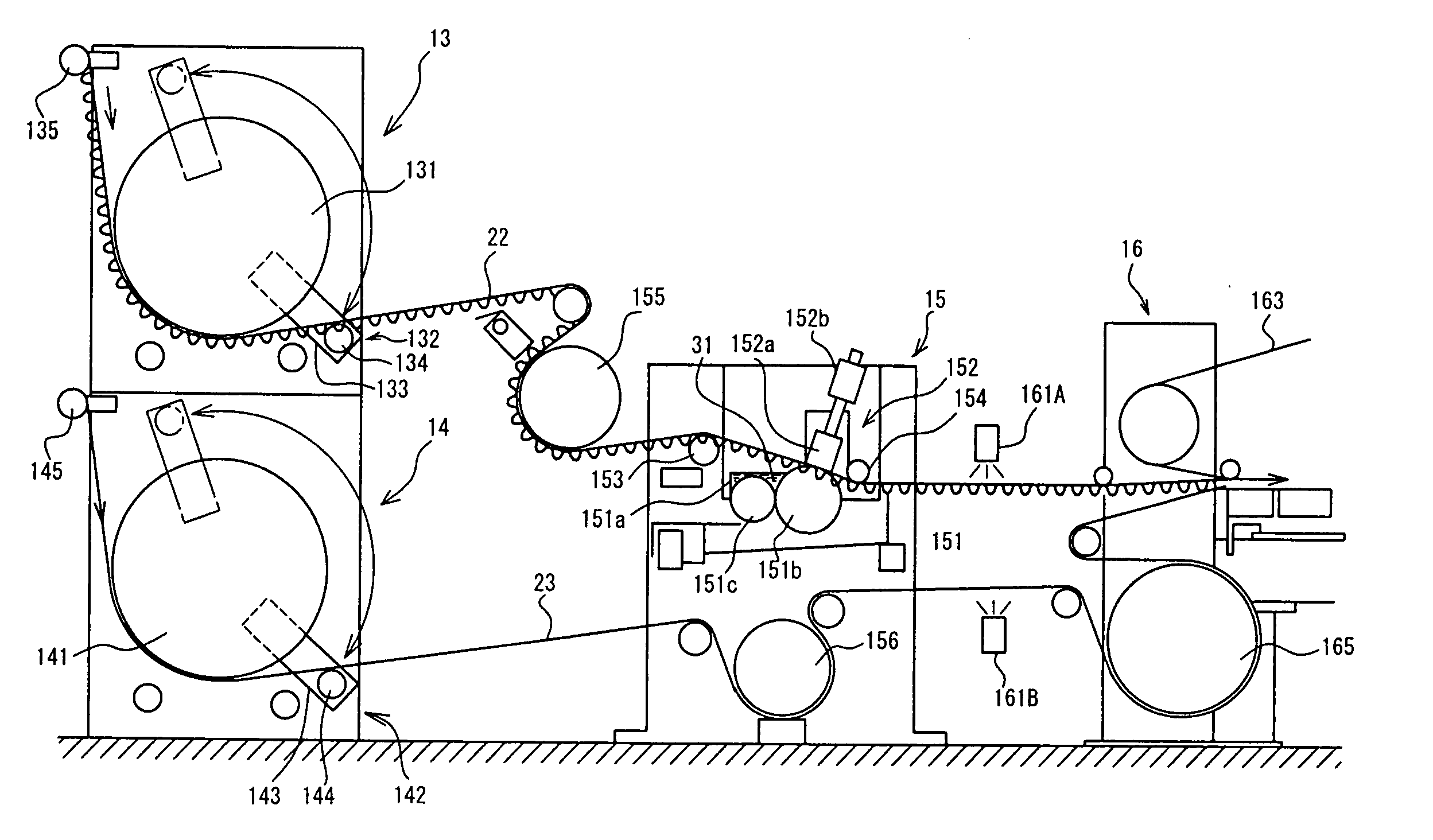
[0346] The corrugated-board fabrication machine 1 of this embodiment includes a wrap roll 40 for a top liner 23 (a top liner wrap roll) and a wrap roll 41 for a single-face web 22 (a wrap roll for a single-face web) in addition to the parts and elements of the corrugated-board fabrication machine 1 of the ninth embodiment shown in FIG. 17. Here, the wrap roll 40 for a top liner is disposed between the top liner preheater 14 and the double facer 16, and the wrap roll 41 for a single-face web is disposed between the single-face web preheater 13 and the glue machine 15.

[0347] The wrap roll 41 for single-face web will now be illustrated with reference to FIG. 22 to explain the wrap rolls 40 and 41. Guide rolls 41a and 41b are arranged close to the wrap roll 41 for a single-face web and are disposed upstream and downstream of the wrap ro...

eleventh embodiment

(B-3) Eleventh Embodiment

[0354] An eleventh embodiment of the present invention will now be described with reference to FIGS. 24-26. The present embodiment is featured by means to obtain information about a warp status of a corrugated board sheet 25 and the remaining configuration is identical to the ninth embodiment shown in FIG. 21.

[0355] As shown in FIG. 24, the production management machine 2A of this embodiment comprises a warp status judgment section 8A as a substitute for the warp status inputting section (push buttons) 6 of the ninth embodiment. A CCD camera (imaging means) 7 is arranged at the rearmost section of the corrugated-board fabrication machine 1.

[0356] As shown in FIG. 25, the CCD camera 7 is arranged at a stacking section 192 of the stacker 19. Corrugated board sheets 25 are cut by the cut-off device 18, transferred by a plurality of non-illustrated conveyors 191, and then subsequently piled in the stacking section 192. The CCD camera 7 images the side of corru...

twelfth embodiment

(B-4) Twelfth Embodiment

[0362]FIG. 27 schematically shows the main part of the corrugated-board warp detection unit according to a twelfth embodiment.

[0363] In the above eleventh embodiment described with reference to FIG. 24, the warp status judgment section 8A obtains a warp status of a corrugated board sheet 25 based on image data obtained by the CCD camera 7. This embodiment uses variation sensors (variation amount detecting means) 7A and 7B as a substitute for the CCD camera (imaging means) 7 so that a warp status judgment section 8A obtains a status of possible warp of a corrugated board sheet based on measurement data obtained by the variation sensor 7A, 7B.

[0364] As shown in FIG. 27, the variation sensor 7A is slidably attached to the rail 171a, which extends horizontally along the width direction of a corrugated board sheet 25, through a variation sensor mounting member 172a, the rail 171a being slidably attached to a rail 171b, which is fixed to an upper frame 171 at the...


PUM

PropertyMeasurementUnit
current machine stateaaaaaaaaaa
widthaaaaaaaaaa
tensionaaaaaaaaaa

Abstract

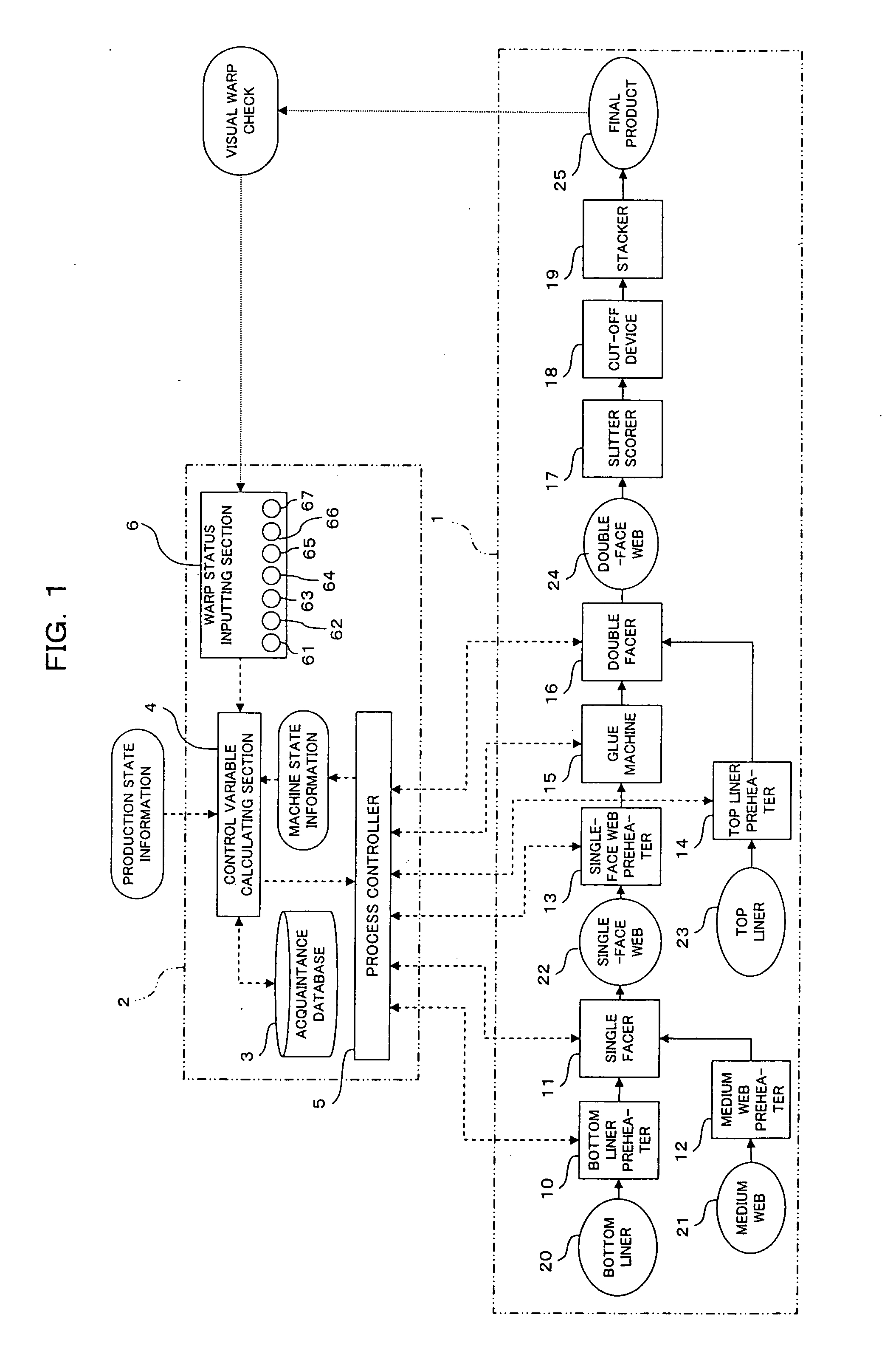
A system for fabricating a corrugated board sheet fabricated includes warp status information obtaining means (6, 6A-6H, 7, 7A, 7B, 8, 8A-8H, 240a, 240b, 241a, 241b) for obtaining warp status information concerning status of the warp of the corrugated board sheet fabricated by a corrugated-board fabrication machine (1); running-state information obtaining means (5, 5A-5H) for obtaining running state information concerning a running state of the corrugated-board fabrication machine (1); control variable calculating means (4, 4A-4H) for calculating a control variable of a particular control factor that affects the warp of the corrugated board sheet and that is one among control factors used to control the corrugated-board fabrication machine (1) based on the warp status information of the corrugated board sheet and the running state information of the corrugated-board fabrication machine (1); and control means (5, 5A-5H) for controlling the particular control factor using the control variable calculated by the control variable calculating means (4, 4A-4H).

Description

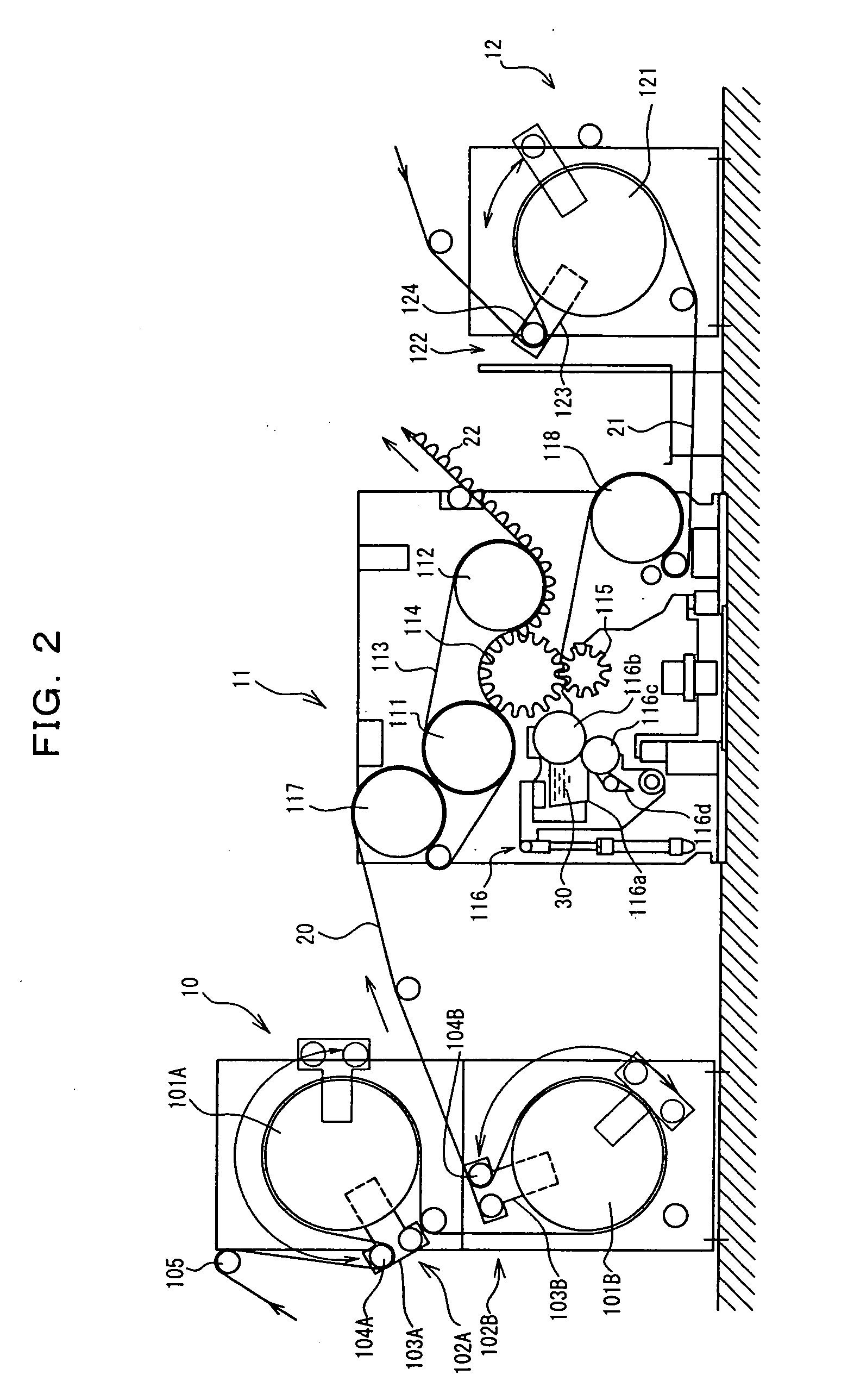
TECHNICAL FIELD [0001] The present invention relates to a system for fabricating a corrugated board sheet, which system includes a preheater, a double facer, a warp detection apparatus, a counter of corrugated board sheets and a warp correction system and the like for a corrugated-board fabrication machine. BACKGROUND OF THE INVENTION [0002] A corrugated board sheet is fabricated by the following process in which a liner (a bottom liner) is glued to a corrugated medium web with adhesive to form a single-face web, gluing the medium web of the single-face web to the other liner (a top liner) and then cutting the fabricated corrugated board into an appropriate length with a cut-off device. During the process, a web (each of a bottom liner, a top liner, a single-face web, and a corrugated board) is heated by a preheater exemplified by a bottom liner preheater, a single-face web preheater and a top liner preheater, and heated by a double facer, and is pasted by a single facer and a glue ...

Claims


Application Information

Patent Timeline
Patent Type & Authority Applications(United States)
IPC IPC(8): B31F1/20B31F1/24B31F1/28B31F1/36B32B39/00
CPCB31F1/24B31F1/36B31F1/284
Inventor ISHIBUCHI, HIROSHIKAWASE, JUNICHISEKI, YUKUHARU
Owner MITSUBISHI HEAVY IND PRINTING & PACKAGING MACHINERY
Learn More