Method of manufacturing a resin-molded stator

Inactive Publication Date: 2005-12-29
HITACHI LTD
View PDF11 Cites 40 Cited by
  • Summary
  • Abstract
  • Description
  • Claims
  • Application Information

AI Technical Summary

Benefits of technology

[0012] The object of the present invention is to provide a resin-molded stator in which the stator coils wound around a plurality of slots and the stator coils at the end of the stator core are molded with resin in order for insulation breakdown between the stator coils and the ground or between the different phases of the stator coils to be prev

Problems solved by technology

The present inventors have found that the prior art practice poses the problem that when a stringent acceleration test simulating the operation mode in which the output of the rotary machine is to be increased from the level under its stopped status to the maximum achievable level within a short time is repeated several times, insulation breakdown occurs between the stator coils and the ground or between the different phases of the stator coils.
In this case, if the stator core and the resin-molded section at the coil end are bonded, a thermal elongation difference reaching 0.35 mm occurs between the stator core and stator

Method used


Image

  • Method of manufacturing a resin-molded stator
  • Method of manufacturing a resin-molded stator
  • Method of manufacturing a resin-molded stator

Examples


embodiment 1

(Embodiment 1)

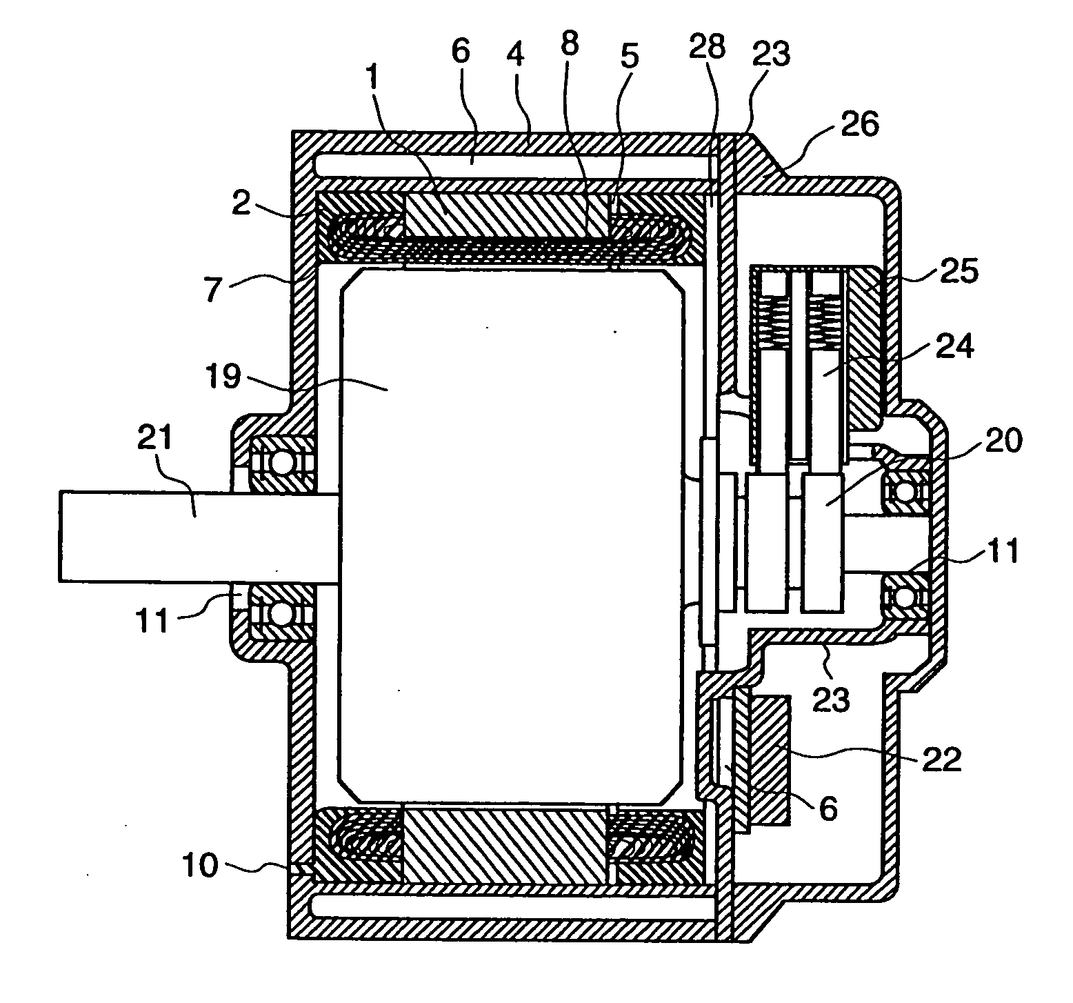
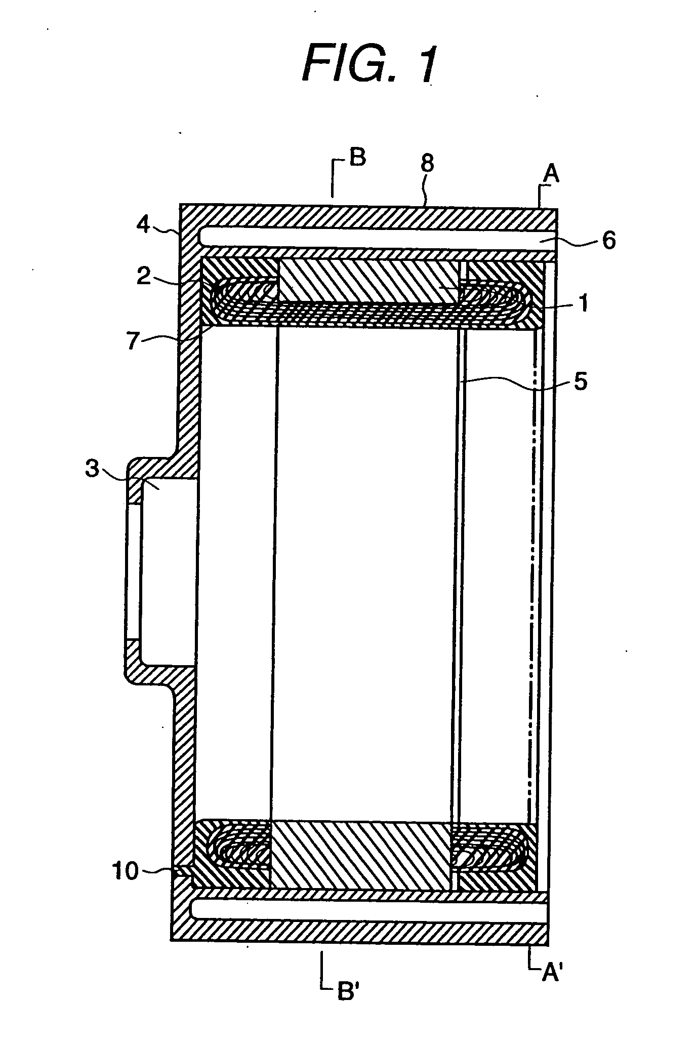
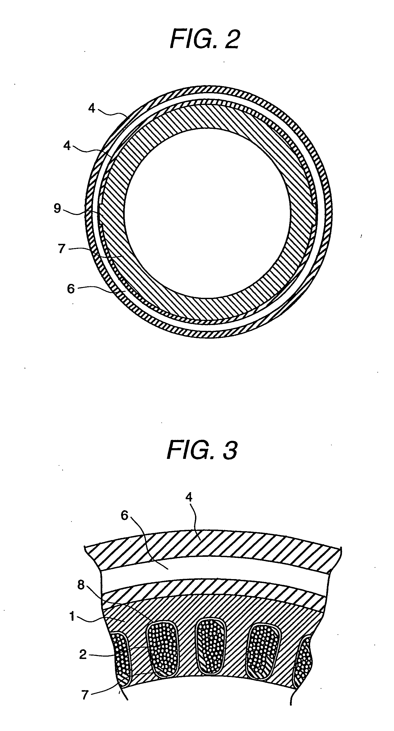
[0033]FIG. 1 is a cross-sectional view of the resin-molded stator showing an embodiment of the present invention. FIG. 2 is a cross-sectional view of the section A-A′ in FIG. 1, and FIG. 3 is a cross-sectional view of the section B-B′ in FIG. 2. The steps taken to manufacture this resin-molded stator are described below. A slot provided in a stator core 1 consisting of laminated electromagnetic steel plates is covered with a liner 8 which is made of a polyamideimides non-woven fabric, and then stator coils 2 each consisting of a conductor provided with insulation are wound around the stator core 1. After this, the stator core 1 around which the stator coils 2 have been wound is built into a housing 4 which has a bearing installation recess 3 at the end of the housing. Of the two surfaces vertical to the axis of the stator core 2, only the surface located at the opposite side to the bearing installation recess 3 in the housing 4 when the stator core 1 is to be built int...

embodiment 2

(Embodiment 2)

[0042]FIG. 6 is a partial cross-sectional view of a brushless rotary machine using the resin-molded stator which employs concentrated winding in the present invention. The steps taken to manufacture this rotary machine are described below. A protrusion provided on a stator core 1 consisting of laminated electromagnetic steel plates is covered with a liner which is made of a polyamideimides non-woven fabric, and then stator coils 2 each consisting of a conductor provided with insulation are wound around the stator core 1. After this, the stator core 1 around which the stator coils 2 have been wound is built into a housing 4. Of the two surfaces vertical to the axis of the stator core 2, only the surface located at the opposite side to the bearing installation recess in the housing 4 when the stator core 1 is to be built into the housing is coated with a polytetrafluoroethylene resin film which has been pre-processed into the same shape as that of the electromagnetic ste...


PUM

PropertyMeasurementUnit
Lengthaaaaaaaaaa
Poweraaaaaaaaaa
Moldableaaaaaaaaaa

Abstract

A highly reliable resin-molded stator not suffering insulation breakdown between the different phases of the stator coils even when the operation mode where the output of a rotary machine using a resin-molded stator in which a stator coil wound around a plurality of slots and a stator coil provided at the stator core end are resin-molded is to be increased from the level under a stopped status to the maximum achievable level within a short time is repeated. Also disclosed is a method of manufacturing such a stator, and a rotary machine using the same. The resin-molded stator of the present invention comprises a stator core, electrically insulated stator coils wound around the plurality of slots or protrusions provided in the axial direction of the stator core, and molding resin with which are molded the stator core and the stator coils located at the aforementioned slots or protrusions and at the stator core end, wherein the resin-molded stator is characterized in that non-adhesive structure is established between the molding resin and at least one of the end faces of the stator core.

Description

[0001] This application is a division of patent application Ser. No. 10 / 390,680, filed Mar. 19, 2003, the entire disclosure of which is incorporated herein by reference. Priority is claimed based on Japanese Patent Application No. 2002-282563, filed Sep. 27, 2002.BACKGROUND OF THE INVENTION [0002] 1. Field of the Invention [0003] The present invention relates to a resin-molded stator, a method of manufacturing the same, and a rotary machine using the same. [0004] 2. Description of the Prior Art [0005] Conventional resin-molded stators and rotary machines using the same employ the structure where, as disclosed in Japanese Application Patent Laid-Open Publication No. 08-223866, Japanese Application Patent Laid-Open Publication No. 09-157440, and Japanese Application Patent Laid-Open Publication No. 10-51989, the stator coil wound around the plurality of slots or bumps in the stator core, and the stator coil at the end of the stator core are molded with resin and the molding resin and ...

Claims


Application Information

Patent Timeline
IPC IPC(8): H02K3/34H02K5/08H02K3/44H02K15/12H02K15/14
CPCH02K5/08Y10T29/49009Y10T428/256H02K15/14Y10T428/31681Y10T428/31786
Inventor AMAGI, SHIGEOKOIZUMI, OSAMU
Owner HITACHI LTD
Why Eureka
Try Eureka