Method and apparatus for dissipating shaft charge

a technology of shaft charge and dissipation method, which is applied in the direction of current collectors, dynamo-electric machines, supports/encloses/casings, etc., can solve the problems of rotor charge accumulation, damage to mechanical components of the motor, and rotor charge accumulation, so as to facilitate the dissipation of shaft charge and mitigate the likelihood of damage in the device

Inactive Publication Date: 2005-12-29
RELIANCE ELECTRIC TECH
View PDF6 Cites 42 Cited by
  • Summary
  • Abstract
  • Description
  • Claims
  • Application Information

AI Technical Summary

Benefits of technology

[0007] According to one embodiment, the present invention comprises an apparatus for use with an electrical device, such as an electric motor and / or various rotatable components of the electric motor. However, as discussed above, the present invention is applicable to a number of devices that employ rotatable elements, such as gearboxes, conveyor systems, and belt drives, to name a few. The apparatus comprises an explosion-proof enclosure and a dissipation member nonrotatably disposed in the enclosure. When installed with respect to the electrical device, the dissipation member of the exemplary apparatus generally abuts a rotatable member of the device, which is at least partially disposed within the explosion-proof enclosure. To dissipate charge developed in the rotatable member during operation of the electrical device, the dissipation member of the exemplary apparatus is configured to electrically couple the rotatable member to ground. Advantageously, by dissipating the charge or voltage in the rotatable member, the likelihood of damage due to arcing and bearing currents (Ib) may be mitigated in the bearing assembly that supports the rotatable member.
[0008] According to another exemplary embodiment, the present invention provides an electric motor. The electric motor comprises a rotor, stator, and bearing assembly disposed within an explosion-proof motor housing or enclosure. The electric motor also includes a brush member disposed in the explosion-proof motor housing as well. In the exemplary motor, the brush member is configured to generally abut the rotor shaft and to facilitate dissipation of shaft charge developed in the rotor shaft during operation of the motor. Because the brush member is disposed within the explosion-proof motor enclosure, the exemplary motor provides applicability to certain hazardous environments, such as those found in petroleum and mining applications, for example. Moreover, the brush member can be configured to impart a desired voltage signal onto the shaft.
[0009] According to yet another exemplary embodiment, the present invention provides an apparatus for use with a device having a rotatable device member. The exemplary apparatus comprises a self-contained explosion-proof enclosure. The apparatus also includes a rotatable shaft at least partially disposed in the explosion-proof enclosure and supported by a bearing assembly that is also housed in the explosion-proof enclosure. To engage with the rotatable device member, the rotatable shaft includes a coupling mechanism configured to couple the rotatable device member and the rotatable shaft mechanically and electrically with respect to one another. The exemplary apparatus also includes a dissipation member nonrotatably housed in the explosion-proof enclosure such that the dissipation member is configured to generally abut the rotatable shaft. To mitigate the likelihood of damage in the device due to charge build-up in the rotatable device member during operation of the device, the dissipation member is configured to couple the rotatable shaft and, as such, the rotatable device member electrically to ground.
[0010] As yet another exemplary embodiment, the present invention provides a method for dissipating charge build-up in a rotatable member of the device during operation of the device. The method comprises disposing a dissipation brush in an explosion-proof enclosure such that the dissipation brush is configured to generally abut the rotatable device member that is also at least partially disposed in the explosion-proof enclosure. Additionally, the method comprises electrically coupling the dissipation brush to ground. Advantageously, the exemplary method mitigates the likelihood of damage within a bearing assembly of the device due to arcing and bearing currents, for example.

Problems solved by technology

Electrostatic coupling, however, results from a number of situations in which rotor charge accumulation can occur.
For example, ionized or high velocity air passing over a rotor may cause rotor charge accumulation.
Unfortunately, bearing currents (Ib) and / or arcing within the bearing can cause damage to mechanical components of the motor.
For example, if Vrg reaches a sufficient threshold value, arcing occurs between the races of the bearing and the rolling elements within the bearing, leading to localized melting and rehardening of the mechanical components of the bearing, for instance.
This material is not as robust as the original bearing material and can lead to fatigue failure—even under relatively light bearing loads.
A bearing surface with untempered matensite leads to pitting and fluting of the bearing components and may cause the bearing assembly to malfunction or to fail prematurely.
Additionally, continued bearing currents (Ib) produce heat that, over time, leads to premature degradation of the bearing lubricant, which ultimately can result in higher maintenance costs and downtime.
In a hazardous location, such arcing has the potential to cause ignition of the hazardous materials.
However, traditional dissipation brush devices are not suitable for use in hazardous environments.
For example, traditional dissipation brush devices fail to sufficiently account for the potential of danger due to electrical arcing between the rotor shaft and the dissipation brush, for instance.
Accordingly, traditional dissipation brush devices are not suitable for use in many mining, industrial, and petroleum applications, where the ignition of a combustible atmosphere, for example, is a relevant concern.

Method used


Image

  • Method and apparatus for dissipating shaft charge
  • Method and apparatus for dissipating shaft charge
  • Method and apparatus for dissipating shaft charge

Examples


Embodiment Construction

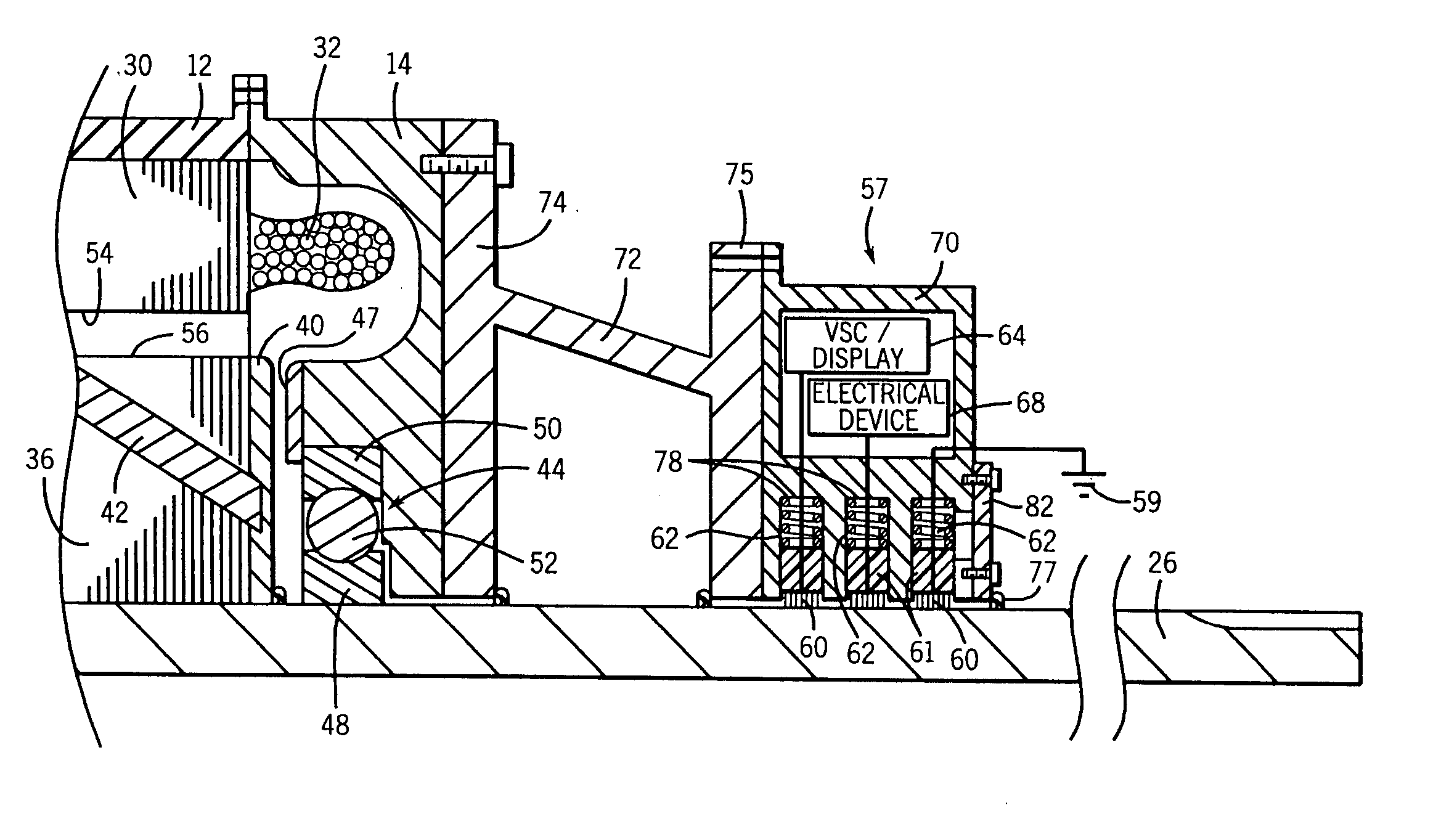
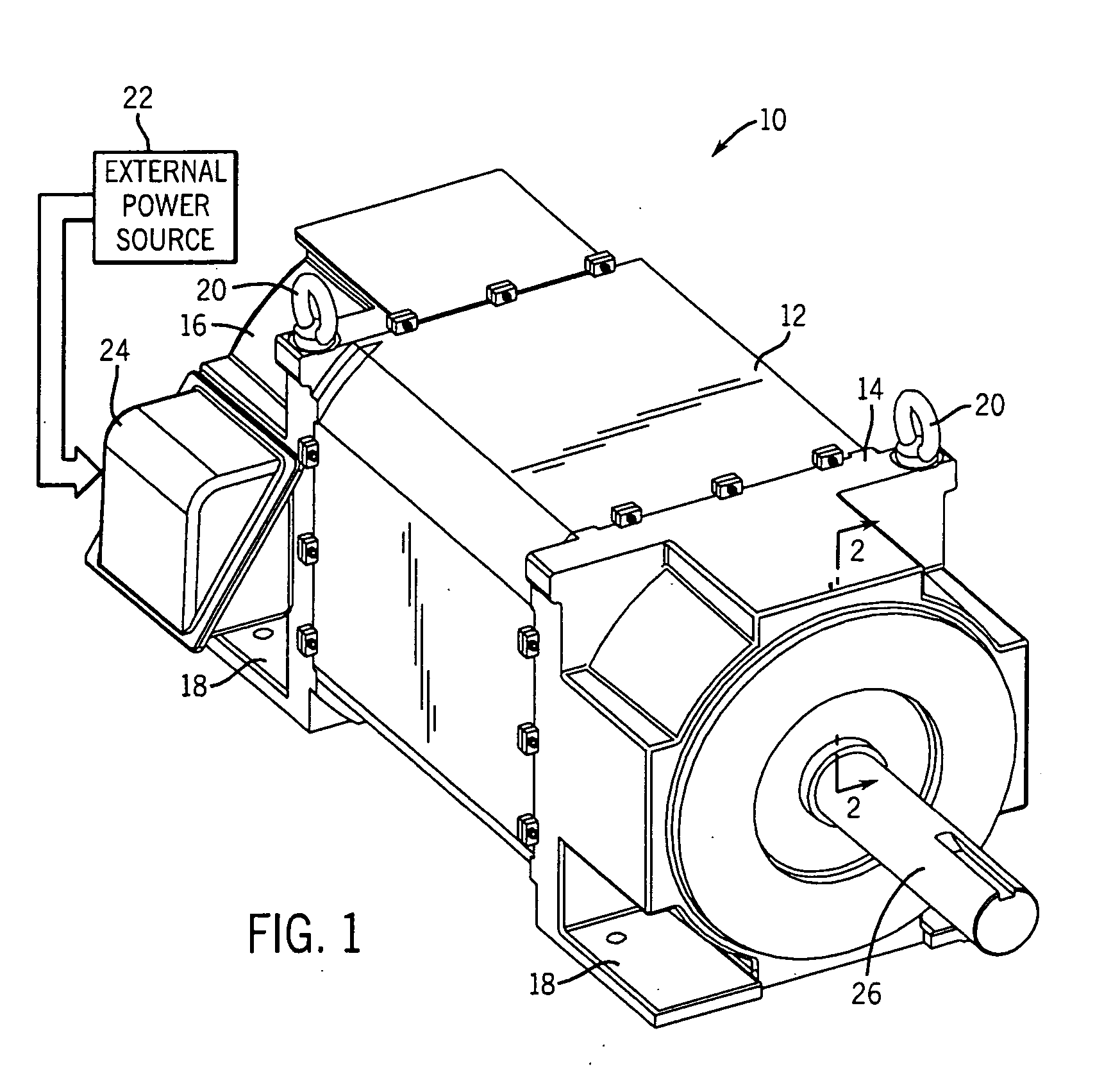
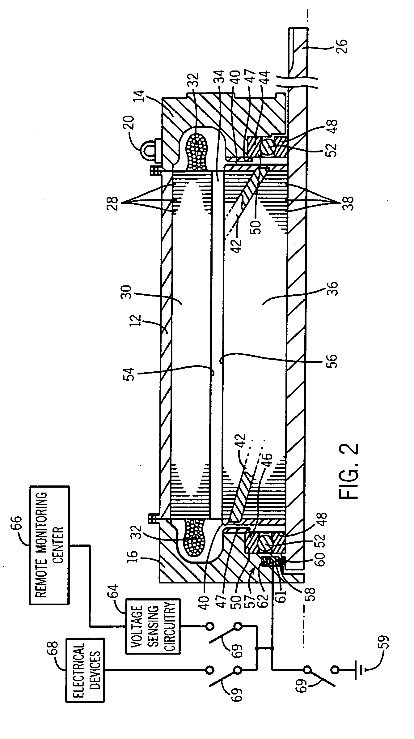
[0016] As discussed in detail below, embodiments of the present invention provide apparatus and methods for dissipating charge build-up within rotatable members of devices operable in hazardous environments. Although the discussion regarding the present invention focuses on electric motors, the present invention is equally applicable to a number of applications in which a rotatable member develops charge during operation. For example, the present invention is applicable to conveyor systems, gearboxes, and drive mechanisms, to name but a few applications. Additionally, the term “explosion-proof” appears throughout the present discussion to describe various items. As employed herein, the term “explosion-proof” refers to an enclosure that is configured to withstand the pressure of an explosive mixture exploding inside the enclosure and to prevent the propagation of the explosion to the atmosphere surrounding the enclosure. By way of example, associations, such as the National Electrica...


PUM


Abstract

The present invention relates generally to dissipation of shaft charge. According to an exemplary embodiment, the present invention provides a charge-dissipating device that includes a dissipation member disposed in an explosion-proof enclosure. When mounted to a rotatable shaft of an electric motor, for example, the dissipation member is configured to generally abut against the rotatable shaft. The dissipation member dissipates shaft-charge developed in the rotatable shaft during operation of the motor. By dissipating shaft charge, the likelihood of arcing and / or bearing current (Ib) occurrences are reduced or eliminated. In accordance with another exemplary embodiment, a transmission member is configured to impart a voltage signal onto the shaft.

Description

BACKGROUND [0001] The present invention relates generally to electromechanical systems, such as an electric motor. Although the following discussion focuses on electric motors, the present invention affords benefits to a number of electromechanical systems and devices that have rotatable elements. For example, the present invention is equally applicable to rotatable elements in gearboxes, press rolls, and conveyor systems, to name a few applications. Indeed, devices comprising shafts that acquire a charge can benefit from the present invention. Additionally, the invention could also be utilized to impose a voltage onto a rotatable shaft, for instance. [0002] Electric motors of various types are commonly found in industrial, commercial and consumer settings. In industry, such motors are employed to drive various kinds of machinery, such as pumps, conveyors, compressors, fans and so forth, to mention only a few. Such motors generally include a stator, comprising a multiplicity of coil...

Claims


Application Information

Patent Timeline
Patent Type & Authority Applications(United States)
IPC IPC(8): H01R39/38H02K5/10H02K5/12H02K5/136H02K5/14H02K11/00H02K13/00
CPCH02K5/136H02K11/0089H02K5/14H02K11/40
Inventor ORDERS, MARCUS D.WOODSON, WILLIAM T.SCHIFERL, RICH F.MELFI, MICHAEL J.
Owner RELIANCE ELECTRIC TECH
Why Eureka
Try Eureka