DC-DC converter

a converter and dc technology, applied in the direction of electric variable regulation, process and machine control, instruments, etc., can solve the problems of increasing switching loss, inviting a cost increase, and large loss, and achieve the effect of reducing ripple voltage and reducing switching loss

Inactive Publication Date: 2005-12-29
MINEBEA CO LTD
View PDF12 Cites 19 Cited by
  • Summary
  • Abstract
  • Description
  • Claims
  • Application Information

AI Technical Summary

Benefits of technology

[0013] The present invention has been made in light of the above problems, and it is an object of the present invention to provide a DC-DC converter which enables reduction of switching loss, is capable of dealing with an extensive variance in input and output voltage, and which enables easy reduction of ripple voltage.
[0024] According to the DC-DC converter of the present invention, the resonance coil includes the first and second windings, and zero-switching is realized by the series circuit composed of the first winding, the clamping capacitor and the auxiliary switching element, whereby the switching loss of the main and auxiliary switching elements and the recovery current of the rectifier diode can be reduced, and PWM control can be performed in an extensive input and output voltage range. Also, a voltage across both terminals of the choke coil can be controlled by induced electromotive force generated at the second winding of the resonance coil, whereby a ripple voltage can be reduced without adding a low-pass filter and increasing the capacitance of the capacitors, which contributes to reducing cost and dimension.

Problems solved by technology

Since the switching loss is increased due to a higher frequency in performing on-off control, a serious problem is raised if frequency is increased for the purpose of reducing the inductance of a choke coil and the capacitance of an output capacitor to thereby reduce dimension and weight of an apparatus.
Also, another problem is that when a reverse bias is applied to the rectifier diode D3 due to the field effect transistor Q1 turned off, a large recovery current is caused to flow through the rectifier diode D3 from the cathode terminal toward the anode terminal at a reverse recovery time, and a large loss is incurred.
Also, since the above-described DC-DC converter produces a larger output ripple voltage than the DC-DC converter 100 shown in FIG. 11, the capacitance of an output capacitor must be increased, and / or a low-pass filter must be added, thus inviting a cost increase.

Method used


Image

  • DC-DC converter
  • DC-DC converter
  • DC-DC converter

Examples


Embodiment Construction

[0039] Preferred embodiments of the present invention will hereinafter be described with reference to the accompanying drawings.

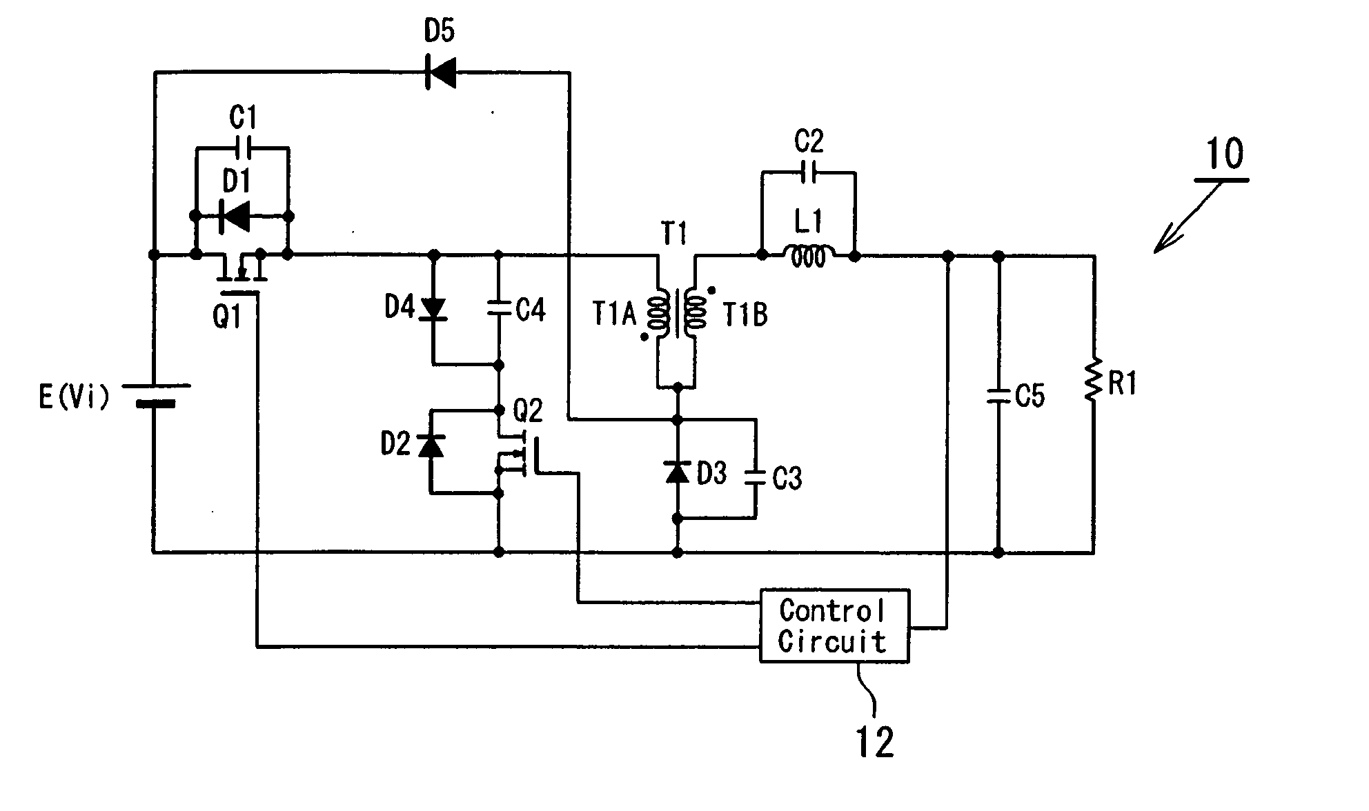
[0040] Referring to Fig. a DC-DC converter 10 according to a first embodiment of the present invention includes a main switching element Q1, a choke coil L1, an output capacitor C5, a rectifier diode D3, a resonance coil T1, an auxiliary switching element Q2, a clamping capacitor C4, and a control circuit 12, wherein E is a power supply with a voltage Vi, and R1 is a resistor as load.

[0041] The main switching element Q1 is preferably constituted by a field effect transistor, and a diode D1 and a capacitor C1 which are connected in parallel to the main switching element Q1 represent a body diode and drain-source junction capacitance, respectively, incorporated in the field effect transistor. The auxiliary switching element Q2 is preferably constituted by a field effect transistor, and a diode D2 connected to the auxiliary switching element Q2 represents a ...


PUM


Abstract

A DC-DC converter is structured such that a main switching element has one terminal connected to one terminal of a DC power supply and has the other terminal connected to one terminal of a first winding of a resonance coil, a choke coil has one terminal connected to one terminal of a second winding of the resonance coil and has the other terminal connected to one terminal of an output capacitor, a rectifier diode has one terminal connected to the connection of the first and second windings and has the other terminal connected to the other terminal of the output capacitor and also to the other terminal of the DC power supply, and a series circuit including an auxiliary switching element and a clamping capacitor is provided between the other terminal of the DC power supply and the connection of the main switching element and the first winding.

Description

BACKGROUND OF THE INVENTION [0001] 1. Field of the Invention [0002] The present invention relates to a DC-DC converter, and more particularly to a DC-DC converter, in which switching loss and output ripple voltage can be reduced. [0003] 2. Description of the Related Art [0004] A DC-DC converter, which converts an input DC voltage into an intended stable DC voltage by switching-control of a semi-conductor device, is highly efficient and can be easily reduced in dimension and weight, and therefore constitutes a vital part in power supplies in various electronic apparatuses, control of electric machinery based on inverter technology, and circuits for lighting various discharge lamps. [0005]FIG. 11 is a circuitry of a conventional step-down DC-DC converter 100. The DC-DC converter 100 includes a field effect transistor Q1, a rectifier diode D3, a choke coil L1, an output capacitor C5, and a control circuit 102, where E is a DC power supply with a voltage Vi, R1 is a resistor as load, an...

Claims


Application Information

Patent Timeline
Patent Type & Authority Applications(United States)
IPC IPC(8): H02M1/34H02M3/155H02M3/158H02M3/335
CPCH02M1/34H02M3/158Y02B70/1491H02M2001/342H02M3/33569Y02B70/10H02M1/342H02M3/33571H02M3/01
Inventor IWAMOTO, KAZUYUKIYAMASHITA, MASAYA
Owner MINEBEA CO LTD
Why Eureka
Try Eureka