
Dynamic test pattern composition for image-analysis based automatic machine diagnostics

a technology of automatic machine diagnostics and test patterns, applied in the direction of instruments, visual presentations, computing, etc., to achieve the effect of reducing maintenance costs and improving customer satisfaction

Inactive Publication Date: 2005-12-29
XEROX CORP
View PDF22 Cites 48 Cited by
  • Summary
  • Abstract
  • Description
  • Claims
  • Application Information

AI Technical Summary

Benefits of technology

[0010] The present invention is directed to an improved system and method wherein the need to print entire test patterns, over several print-analysis iterations, is simplified and expedited. The present invention employs a dynamic test pattern composition process and system, wherein the test targets required for analysis are selected and printed on a test pattern rather than simply printing several patterns having desired test targets. The dynamic selection and printing of test targets enables better utilization of the test pattern and is more efficient in that it potentially reduces the number of printing-analysis cycles. At a minimum, the present invention reduces the time and effort to print the test patterns and to scan the printed samples into electronic form so that they can be further analyzed.
[0013] In accordance with an aspect of the present invention, there is provided a method for dynamic test pattern generation, including the steps of: automatically selecting a set of test targets as a function of the probability of possible defects and machine performance data and to maximize an optimization criteria; and placing the set of test targets on a digital test pattern.

Problems solved by technology

Given the large number of operating parameters that need to be tracked during operation, a specific defect at a certain level may or may not be a significant problem.
Image quality problems occurring in a document processing system are often identified by applying image processing and pattern recognition techniques to analyze specific test patterns.
Generation of the next test pattern is a constrained optimization problem wherein the optimization criteria is often to maximize the discriminating power between the failure modes of sets of targets or the information obtained from the set of test targets.

Method used


Image

  • Dynamic test pattern composition for image-analysis based automatic machine diagnostics
  • Dynamic test pattern composition for image-analysis based automatic machine diagnostics
  • Dynamic test pattern composition for image-analysis based automatic machine diagnostics

Examples


Embodiment Construction

[0035] The following description begins with a discussion of document processing systems, in general, and defect analysis in order to characterize the general embodiment and context within which the present invention will be explained in detail.

[0036] As used in this application, document processing systems, include analog and digital copiers, printers, scanners, facsimiles, and multifunction machines, each of which includes an output device. Said systems include those based on all direct and indirect marking technologies, both color and black and white, such as xerography, ink jet, liquid ink, lithography, and the like.

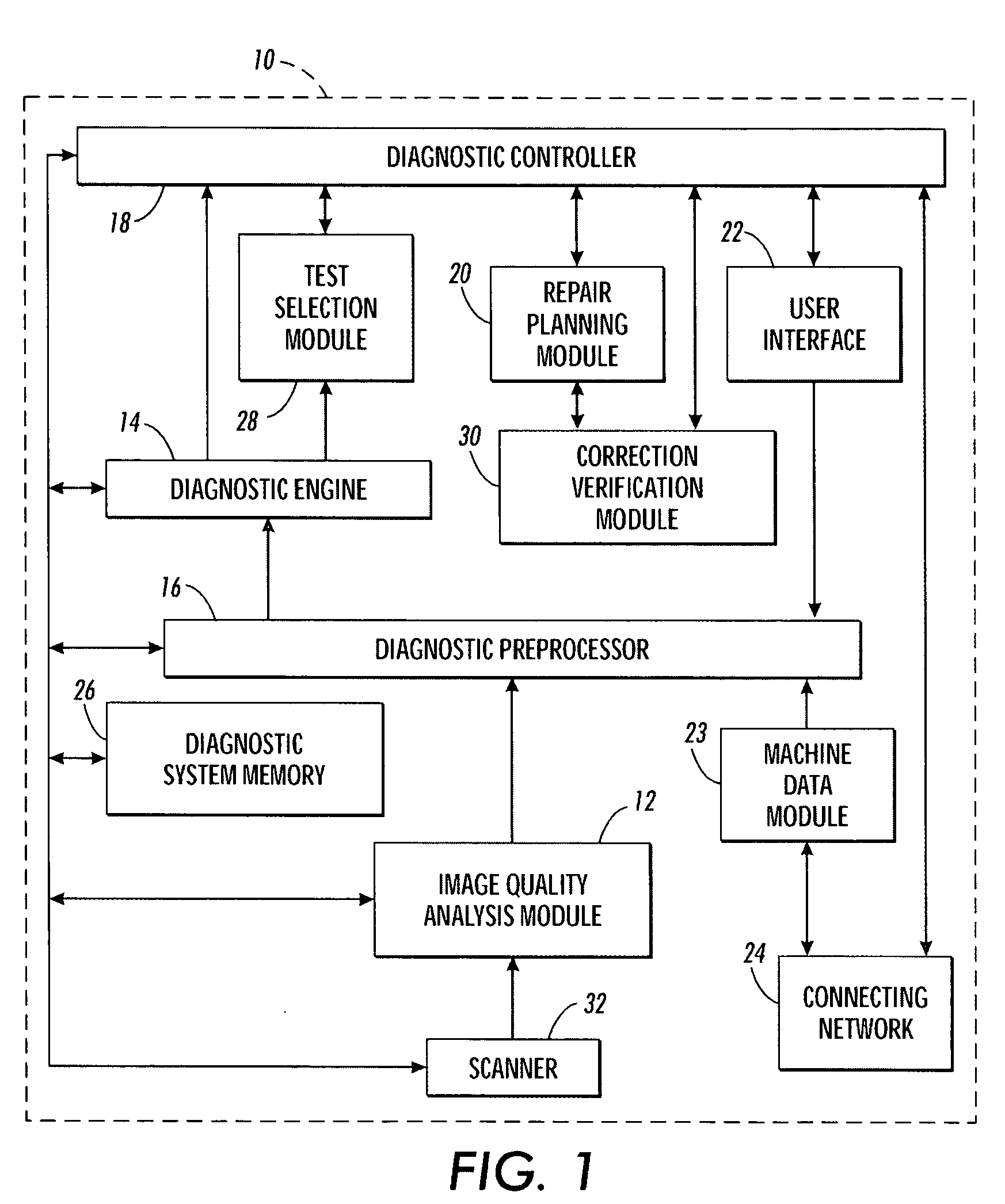
[0037] Reference is now being made to FIG. 1, which illustrates Diagnostic System 10 for analysis of defects often experienced in such systems as identified above and, as a consequence, are frequent causes of service calls. Analysis of lines, streaks, and bands is no easy task as such defects can reflect as many as thirty or more malfunctions occurring within the D...

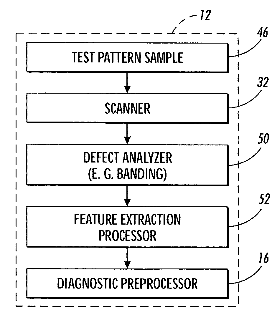
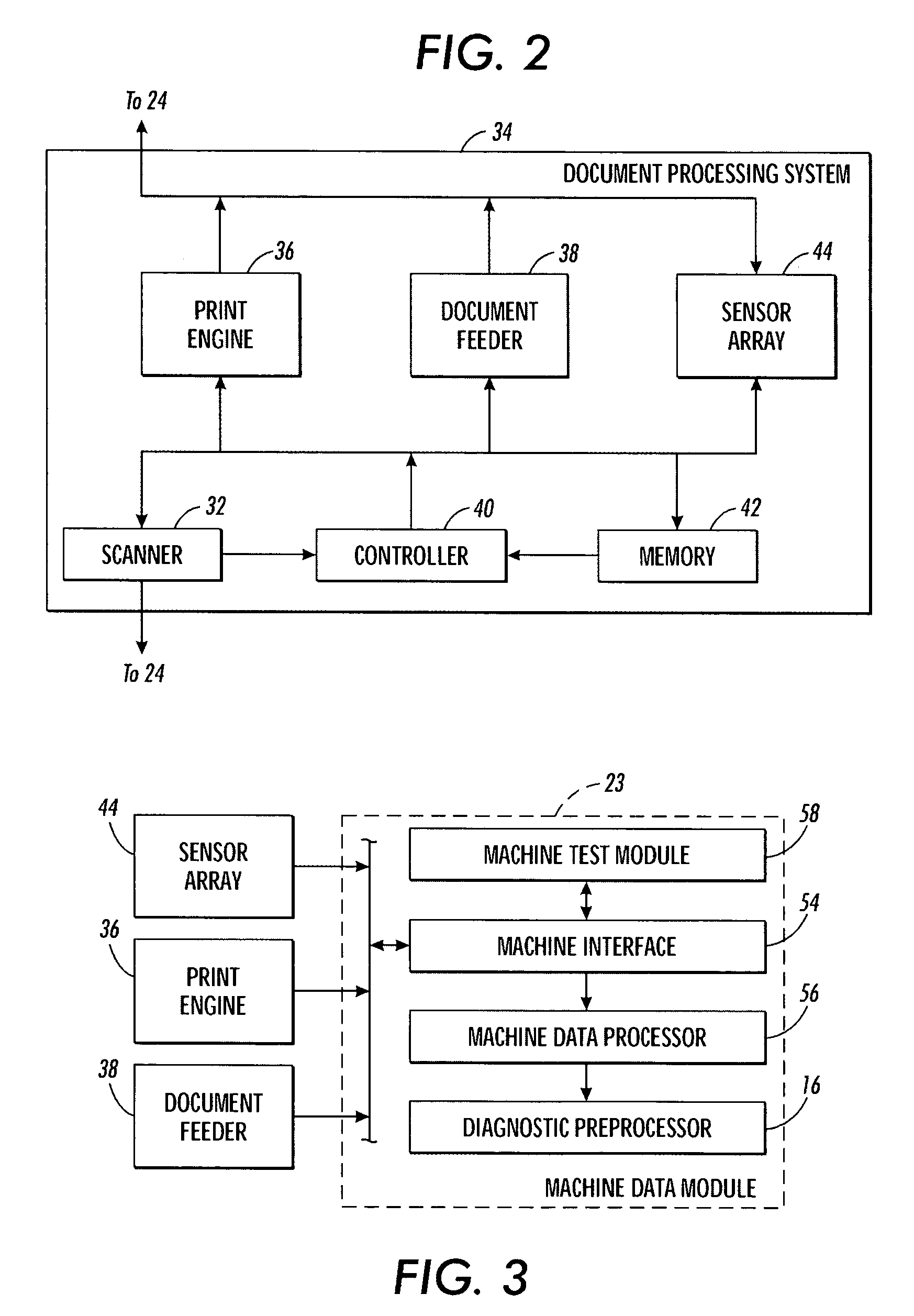

PUM


Abstract

The present invention is directed to a system and method for test target selection in conjunction with dynamic test pattern generation. In the invention, a test pattern page(s) is composed using an optimal set of test targets, which can be accommodated or adjusted to fit within size constraints of the test pattern. The method of the present invention makes use of layout optimization to ensure that related and optimized test targets are accommodated on a single test pattern. For example, it may be preferable to “squeeze in” a smaller-than-normal uniform area target, rather than not to print it at all during a test.

Description

CROSS-REFERENCE [0001] The following U.S. patent is cross-referenced and is hereby incorporated by reference in its entirety for its teachings: “SYSTEMS AND METHODS FOR AUTOMATED IMAGE QUALITY BASED DIAGNOSTICS AND REMEDIATION OF DOCUMENT PROCESSING SYSTEMS” to Sampath et al., U.S. Pat. No. 6,665,425, issued Dec. 16, 2003.FIELD OF THE INVENTION [0002] This invention relates to malfunction diagnosis of defects in document processing systems, and more particularly to the dynamic generation of test pattern(s) based on defect feature analysis and machine data analysis. BACKGROUND AND SUMMARY OF THE INVENTION [0003] In document processing systems, it is well known that customer satisfaction can be improved and maintenance costs reduced if problems with copiers and printers can be detected and resolved before they become serious enough to warrant a service call from the customer. Systems exist that enable printers and copiers to call for service automatically, when sensors detect certain ...

Claims


Application Information

Patent Timeline
IPC IPC(8): B41J29/393G06K9/00
CPCB41J29/393H04N1/00002H04N1/00005H04N1/00015H04N1/00018H04N1/00087H04N1/00045H04N1/0005H04N1/00063H04N1/00068H04N1/00034
Inventor RASMUSSEN, D. RENESAMPATH, MEERADALAL, EDUL N.
Owner XEROX CORP
Learn More