Method and system for a variable speed fan control for thermal management

a fan control and variable speed technology, applied in the direction of motor/generator/converter stopper, dynamo-electric converter control, instruments, etc., can solve the problems of air conditioning units occupying valuable space, radiation detectors losing linearity and failing prematurely, and relatively cumbersome units

Active Publication Date: 2005-12-29
GENERAL ELECTRIC CO
View PDF6 Cites 50 Cited by
  • Summary
  • Abstract
  • Description
  • Claims
  • Application Information

AI Technical Summary

Benefits of technology

[0009] One aspect of the invention is a method for variable speed fan control for thermal management of a device. The method includes disposing a first temperature sensor proximate a variable speed fan; measuring an air temperature of inlet air Tair that cools the device by convection air flow; and configuring a controller to compensate for changes in Tair by varying a convection coefficient (h) which is a function of air velocity to maintain a product of h*ΔT at a constant value; wherein ΔT is a temperature differential between the device (TAD) and Tair.
[0010] Another aspect of the invention is a method for variable speed fan control for thermal management of a A / D card in an imaging system. The method includes: disposing a variable speed fan configured to convectively cool the A / D card for the CT scanner for a data acquisition system (DAS) in operable communication with a plurality of detectors; disposing a first temperature sensor proximate the variable speed fan; measuring an air temperature of inlet air Tair that cools the A / D card by convection air flow; and configuring a controller to compensate for changes in Tair by varying a convection coefficient (h) which is a function of air velocity to maintain a product of h*ΔT at a constant value; wherein ΔT is a temperature differential between the A / D card (TAD) and Tair.
[0011] A further aspect of the invention is a system for variable speed fan control for thermal management of a device includes disposing a first temperature sensor proximate a variable speed fan to measure an air temperature of inlet air Tair that cools the device by convection air flow. A controller is configured to compensate for changes in Tair by varying a convection coefficient (h) which is a strong function of air velocity to maintain the product of h*ΔT at a constant value, wherein ΔT is a temperature differential between the device (TAD) minus Tair. Thus, h is varied by varying air velocity by varying a speed of the variable speed fan.

Problems solved by technology

Because the radiation detectors lose linearity and fail prematurely when heated, they are kept cool.
First, the air conditioning units take up valuable space within the CT scanner gantry.
The units are relatively cumbersome, and limit the amount of space available for the various CT scanner features.
Second, air conditioning units require frequent maintenance.
If the air conditioning unit breaks down, the detectors can overheat during CT scanner use.
Further, the air conditioning units are not readily removable.
Their position within a CT scanners makes it difficult to repair other CT scanner parts and features by inhibiting free access to such parts.
Unfortunately, however, both of these devices are temperature sensitive, with the photo diode responding exponentially to temperature.
Operation of the x-ray source and power supplies generates a large amount of heat that causes the ambient temperature inside the CT system to rise significantly.
It is a very difficult design challenge to control the air temperature variation within a gantry and is subject to a multitude of design constraints such as, room air temperature control, allowable system packaging volume in an existing CT gantry platform (e.g., major components and component placement not easily changed or modified).
Current CT systems have air temperature variations (e.g., 15° C.) which are unacceptable for current DAS / detector design.
Control of the air temperature and flow rate due to gantry rotations is an even more challenging design issue and is not addressed by current system designs and expected to get worse as system rotational speeds increase.
Furthermore, current DAS cooling fans are loud and barely meet audible specifications for such fans.

Method used


Image

  • Method and system for a variable speed fan control for thermal management
  • Method and system for a variable speed fan control for thermal management
  • Method and system for a variable speed fan control for thermal management

Examples


Embodiment Construction

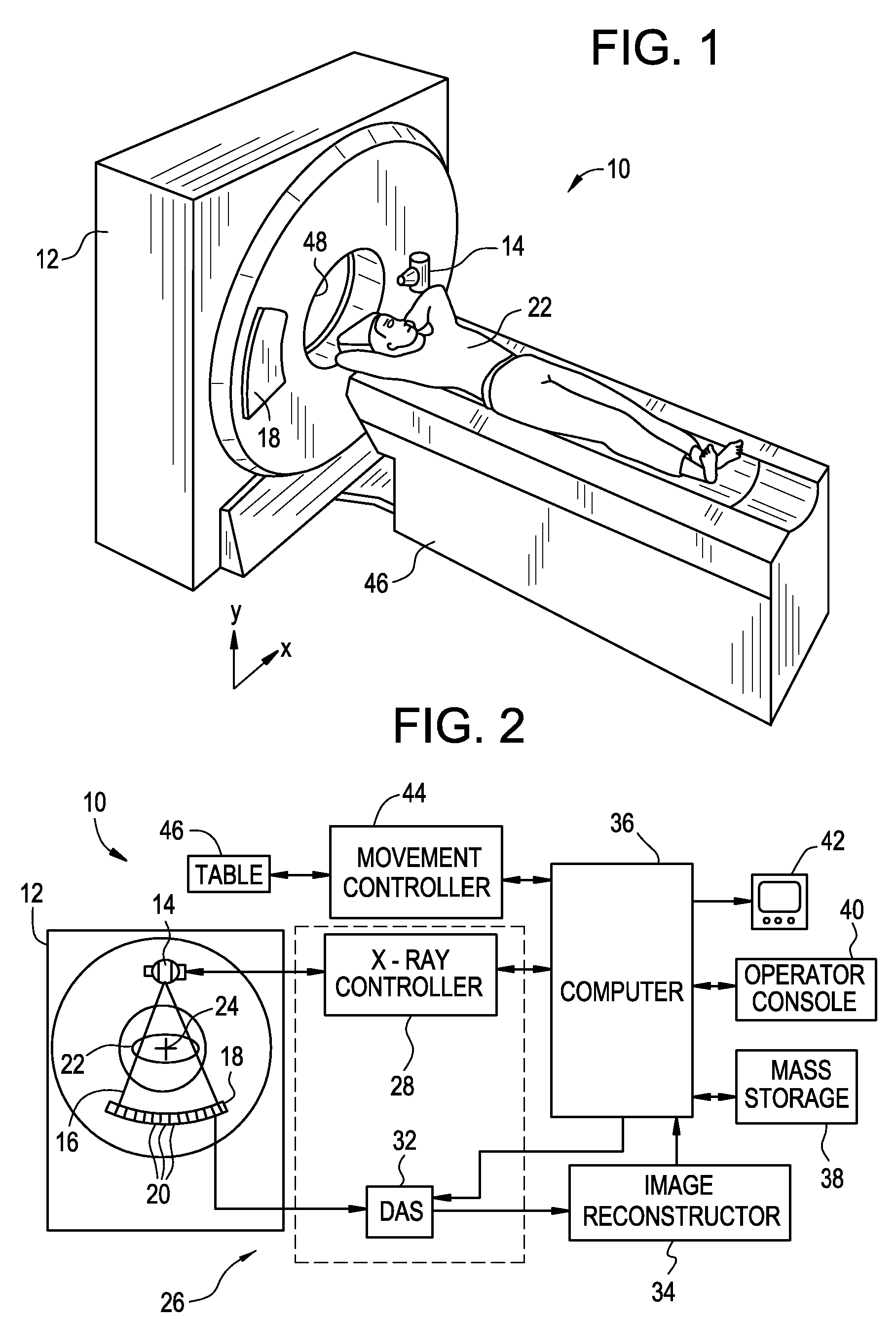
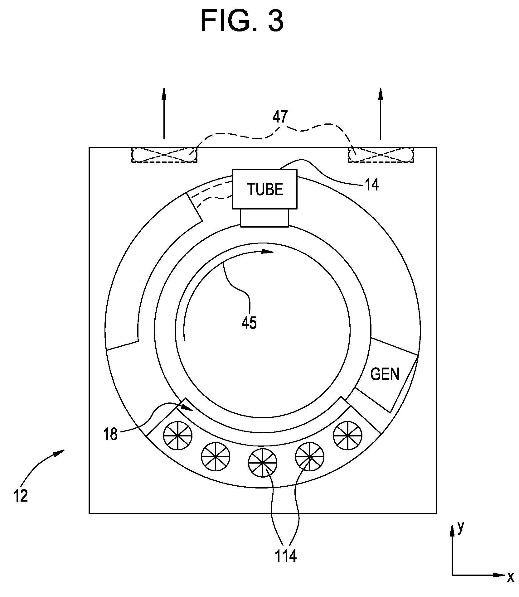
[0022] Referring to FIG. 1, a computed tomography (CT) imaging system 10 is shown as including a gantry 12 representative of a “third generation” CT scanner. The gantry 12 has an x-ray source 14 that projects a beam of x-rays 16 toward a detector array 18 on the opposite side of the gantry 12.

[0023] The detector array 18 is formed by a plurality of detection elements 20 which together sense the projected x-rays that pass through a medical patient 22. Each detection element 20 produces an electrical signal that represents the intensity of an impinging x-ray beam and hence, the attenuation of the beam as it passes through the patient 22. During a scan to acquire x-ray projection data, the gantry housing 12 and the components mounted thereon rotate about a center of gravity or axis 24.

[0024] The operation of the x-ray source 14 is governed by a control mechanism 26 of the CT system 10. The control mechanism 26 includes an x-ray controller 28 that provides power and timing signals to ...


PUM


Abstract

A method and system for variable speed fan control for thermal management of a device includes disposing a first temperature sensor proximate a variable speed fan to measure an air temperature of inlet air Tair that cools the device by convection air flow. A controller is configured to compensate for changes in Tair by varying a convection coefficient (h) which is a strong function of air velocity to maintain the product of h*ΔT at a constant value, wherein ΔT is a temperature differential between the device (TAD) minus Tair. Thus, h is varied by varying air velocity by varying a speed of the variable speed fan.

Description

BACKGROUND OF THE INVENTION [0001] The present disclosure relates generally to a method for cooling a data acquisition system (DAS) and detectors associated with computer assisted tomography (CAT) and in particular, to a method for cooling a DAS / detectors in different air temperatures and air flow rates using a variable speed fan to compensate for rotation of the gantry. [0002] The present disclosure pertains to the art of medical diagnostic imaging and more particularly to computerized tomographic (CT) scanners. The disclosure finds particular application in conjunction with cooling systems associated with CT scanners and will be described with particular reference thereto. It will be appreciated, however, that the invention has broader applications and may be advantageously employed in other environments. [0003] CT scanner cooling systems of the type to which this invention pertains have ordinarily included air conditioning units housed within CT scanner gantries. Such air conditi...

Claims


Application Information

Patent Timeline
Patent Type & Authority Applications(United States)
IPC IPC(8): F04B49/06F04B49/10F04D27/02
CPCA61B6/035Y10S388/934F04D27/004A61B6/4488Y02B30/70
Inventor LACEY, JOSEPH JAMESJOSHI, ASHUTOSH
Owner GENERAL ELECTRIC CO
Why Eureka
Try Eureka