
Method of determining analyte level using subcutaneous electrode

a technology of subcutaneous electrodes and analyte levels, which is applied in the field of in vivo enzyme biosensors, can solve problems such as loss of sensitivity, and achieve the effect of accurate measuremen

Inactive Publication Date: 2005-12-29
THERASENSE
View PDF99 Cites 654 Cited by
  • Summary
  • Abstract
  • Description
  • Claims
  • Application Information

AI Technical Summary

Benefits of technology

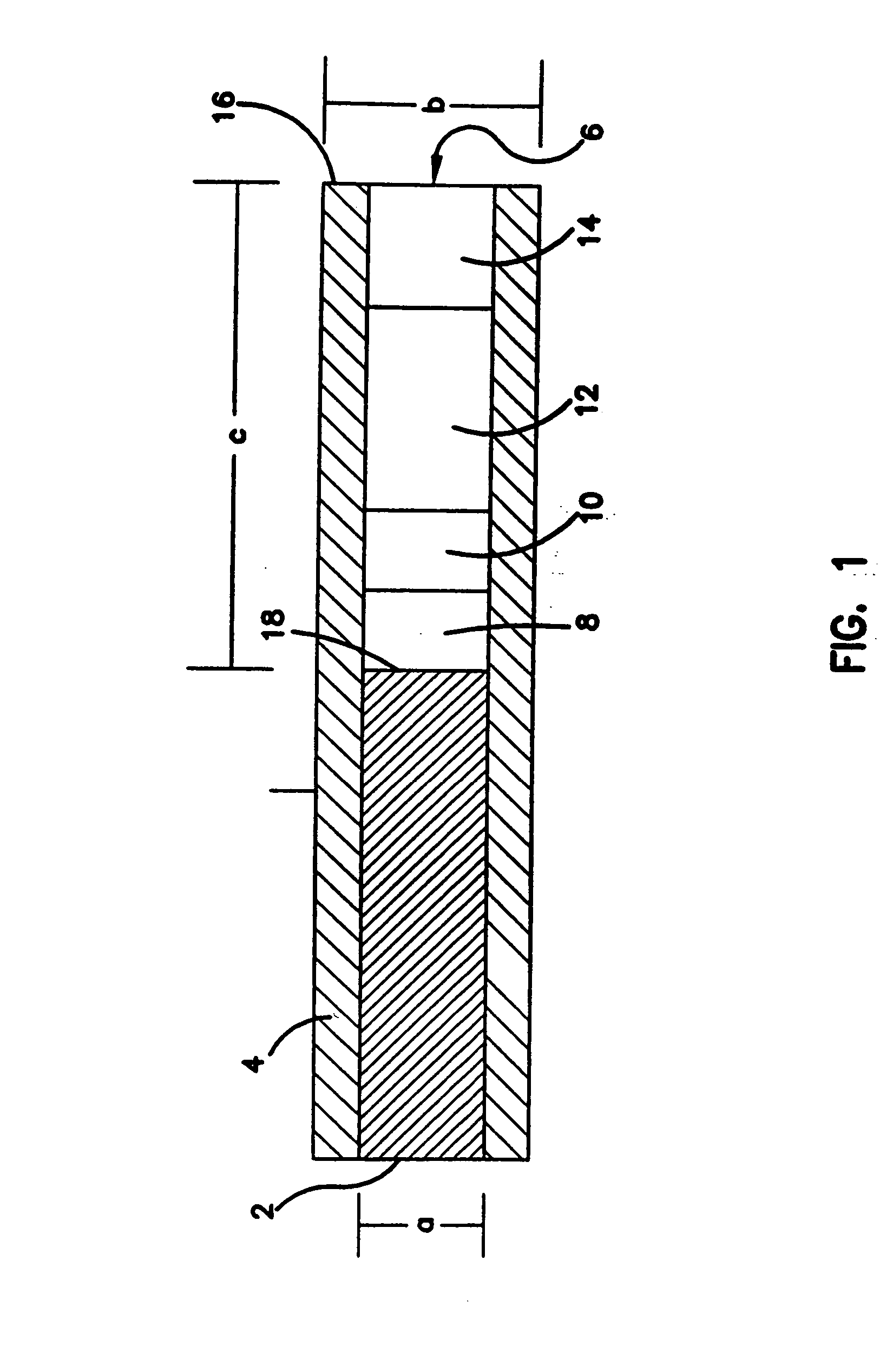
[0011] The active polymer layers, including a sensing layer, a glucose flux-limiting layer, a biocompatable layer, and optionally a peroxidase-based interferant eliminating layer, were protected within the recess against mechanical damage. (The peroxidase-based interferant eliminating layer is not required when a lower redox potential polymer is used, as described above.) The recess and its polymer layers also reduced the transport of glucose to the wire electrode contacting sensing layer.
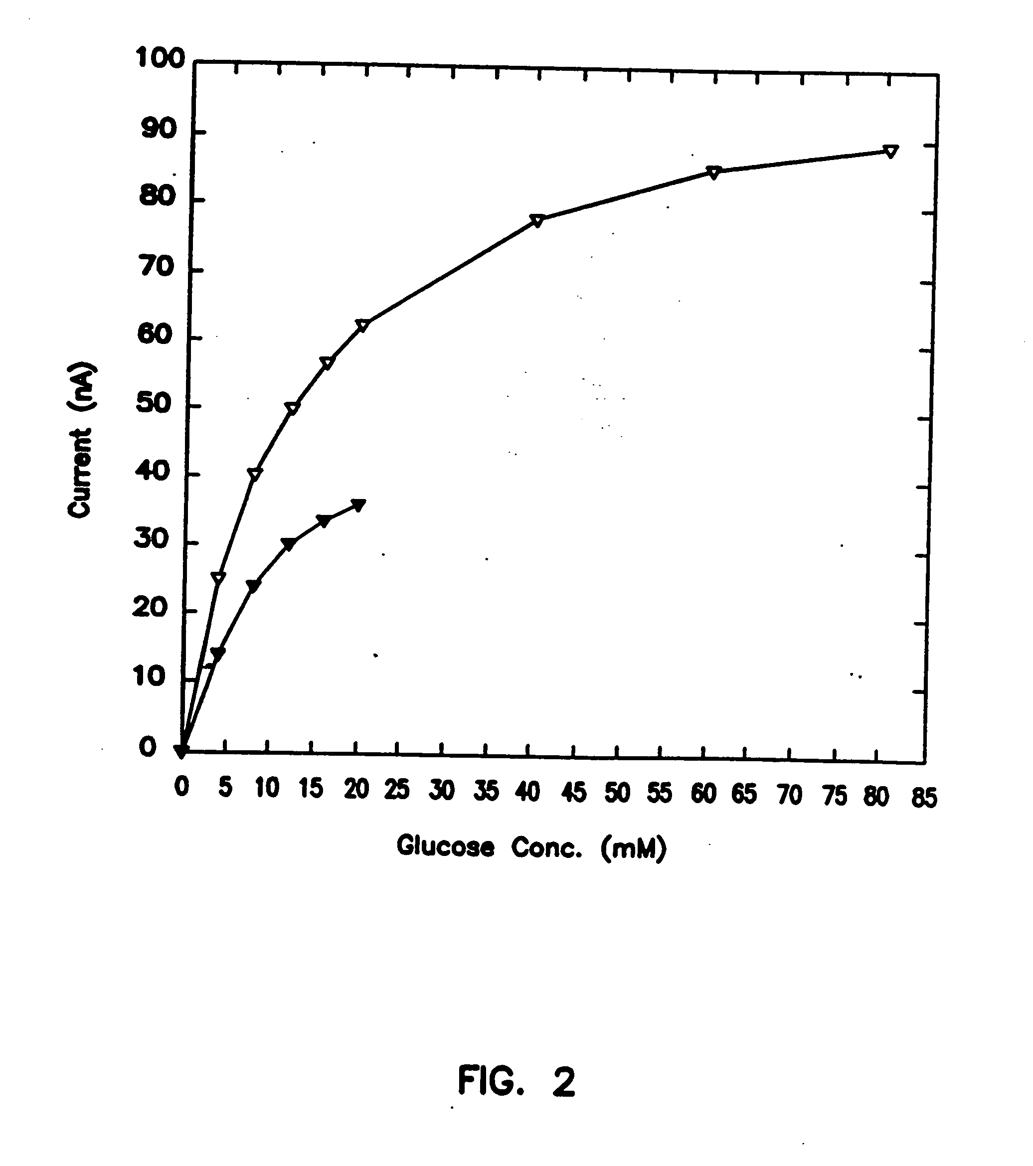
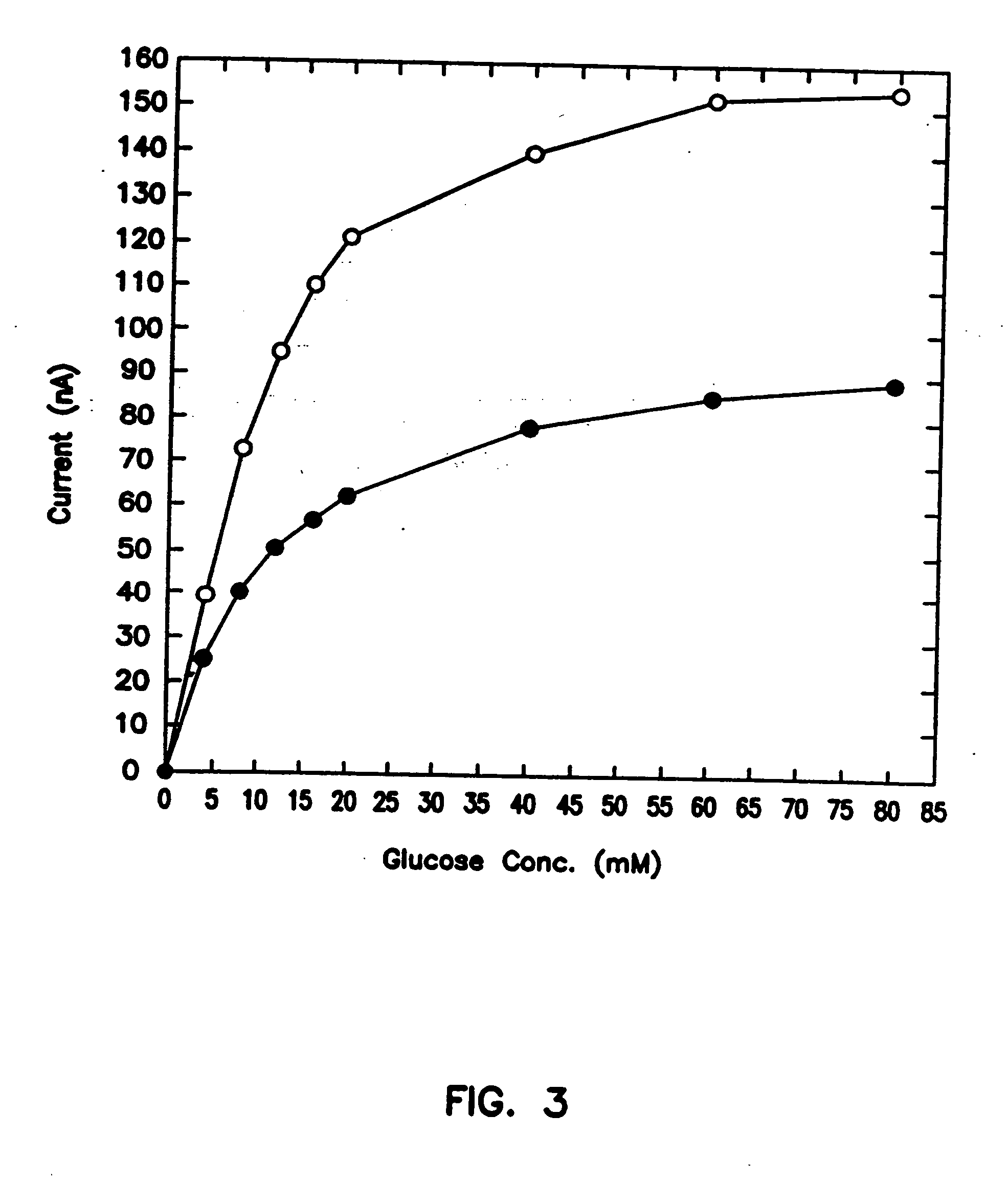
[0012] By limiting the glucose flux, the desired linear response range, spanning the clinically relevant glucose concentration range was obtained. The inventive biosensors are able to accurately measure, for example, approximately 2-30 mμ glucose and approximately 0.5-10 mμ lactate, in vivo. The sensor has no leachable components, and its four crosslinked polymer layers contain only about 5 μg of immobilized material, and only a few nanograms of polymer-bound osmium. Preoxidation of the interferants in one of the four layers makes possible one-point in vivo calibration of the sensor.

Problems solved by technology

Such leaching introduces an unwanted chemical into the body, and also leads to loss in sensitivity, particularly in small sensors.

Method used


Image

  • Method of determining analyte level using subcutaneous electrode
  • Method of determining analyte level using subcutaneous electrode
  • Method of determining analyte level using subcutaneous electrode

Examples


example 1

[0055] Electrode Preparation

[0056] Electrodes were made of a polyamide-insulated 250 μm diameter gold wire, having an outer diameter (O.D.) of 290 μm (California Fine Wire Co., Grover City, Calif.). Heat shrinkable tubing (RNF 100 3 / 64″ BK and 1 / 16″ BK, Thermofit.RTM., Raychem, Menlo Park, Calif.) and a two component silver epoxy (Epo-tek H2OE; Epoxy Tech, Inc., Billerica, Mass.) were used for electrode preparation.

[0057] The glucose sensing layer was made by crosslinking a genetically engineered glucose oxidase (rGOX) (35% purity, Chiron Corp., Emeryville, Calif.) with a polymer derived of poly(vinylimidazole) (PVI), made by complexing part of the imidazoles to [Os(bpy)2C]+ / 2+. The resulting redox polymer, termed PVI-Os, was synthesized -according to a previously published protocol. (Ohara et al., 1993, Anal. Chem., 65:24). Poly(ethylene glycol) diglycidyl ether 400 (PEDGE; Polysciences, Warrington, Pa.) was used as the crosslinker.

[0058] The barrier layer between the sensing an...

example 2

[0088] In Vivo Use of Sensor

[0089] The objective of this experiment was to establish the validity of a one-point in vivo calibration. Two sensors were simultaneously implanted subcutaneously in a rat, one on the thorax, the second between the scapulae. To make the difference between the blood sampled and the subcutaneous fluid proved with the sensors as extreme as possible, i.e., to probe whether the one-point calibration holds even if the organs sampled are different and the sampling sites are remote, blood was withdrawn from the tail vein. Blood glucose levels were periodically measured in withdrawn samples, while the absolute uncorrected sensor current output was continuously monitored.

[0090] In vivo experiments (6-10 hours) were carried out in 300 g male Sprague-Dawley rats. The rats were fasted overnight and prior to the experiment were anaesthetized with an intraperitoneal (i.p.) injection of sodium pentobarbital (65 mg / kg rat wt). An i.p. injection of atropine sulfate (166 ...


PUM

PropertyMeasurementUnit
diameteraaaaaaaaaa
diameteraaaaaaaaaa
diameteraaaaaaaaaa

Abstract

A small diameter flexible electrode designed for subcutaneous in vivo amperometric monitoring of glucose is described. The electrode is designed to allow “one-point” in vivo calibration, i.e., to have zero output current at zero glucose concentration, even in the presence of other electroreactive species of serum or blood. The electrode is preferably three or four-layered, with the layers serially deposited within a recess upon the tip of a polyamide insulated gold wire. A first glucose concentration-to-current transducing layer is overcoated with an electrically insulating and glucose flux limiting layer (second layer) on which, optionally, an immobilized interference-eliminating horseradish peroxidase based film is deposited (third layer). An outer (fourth) layer is biocompatible.

Description

[0001] This application is a Continuation of application Ser. No. 10 / 353,341, filed Jan. 28, 2003, now U.S. Pat. No. 6,881,551, which is a Continuation application of Ser. No. 09 / 997,808, filed Nov. 29, 2001, now U.S. Pat. No. 6,514,718, which is a Continuation application of Ser. No. 09 / 668,221, filed Sep. 22, 2000, now U.S. Pat. No. 6,239,161, which is a Continuation of application Ser. No. 09 / 477,053, filed Jan. 3, 2000, now U.S. Pat. No. 6,162,611, which is a Continuation of application Ser. No. 09 / 356,102, filed Jul. 16, 1999, now U.S. Pat. No. 6,121,009, which is a Continuation of application Ser. No. 08 / 767,110, filed Dec. 4, 1996, now U.S. Pat. No. 6,284,478, which is a continuation of application Ser. No. 08 / 299,526, filed Sep. 1, 1994, now U.S. Pat. No. 5,593,852, which is a continuation-in-part of application Ser. No. 08 / 161,682, filed Dec. 2, 1993, now U.S. Pat. No. 5,356,786, which is a continuation of application Ser. No. 07 / 664,054, filed Mar. 4, 1991, now abandoned, ...

Claims


Application Information

Patent Timeline
Patent Type & Authority Applications(United States)
IPC IPC(8): G01N27/327A61B5/145A61B5/1473A61B5/1486A61B5/1495C12M1/40C12Q1/00C12Q1/54
CPCC12Q1/006C12Q1/54Y10S435/817Y10S435/962Y10S435/917A61B5/1486A61B5/14532A61B5/1495
Inventor HELLER, ADAMPISHKO, MICHAEL V.
Owner THERASENSE
Learn More