Method of manufacturing a semiconductor memory device

a memory device and semiconductor technology, applied in semiconductor devices, capacitors, electrical devices, etc., can solve the problems of failure to provide the desired capacitance, damage to the lower structure, and damage to the elements in the upper structure, so as to achieve the effect of easy increase of the height of the bottom electrod

Inactive Publication Date: 2005-12-29
SAMSUNG ELECTRONICS CO LTD
View PDF6 Cites 55 Cited by
  • Summary
  • Abstract
  • Description
  • Claims
  • Application Information

AI Technical Summary

Benefits of technology

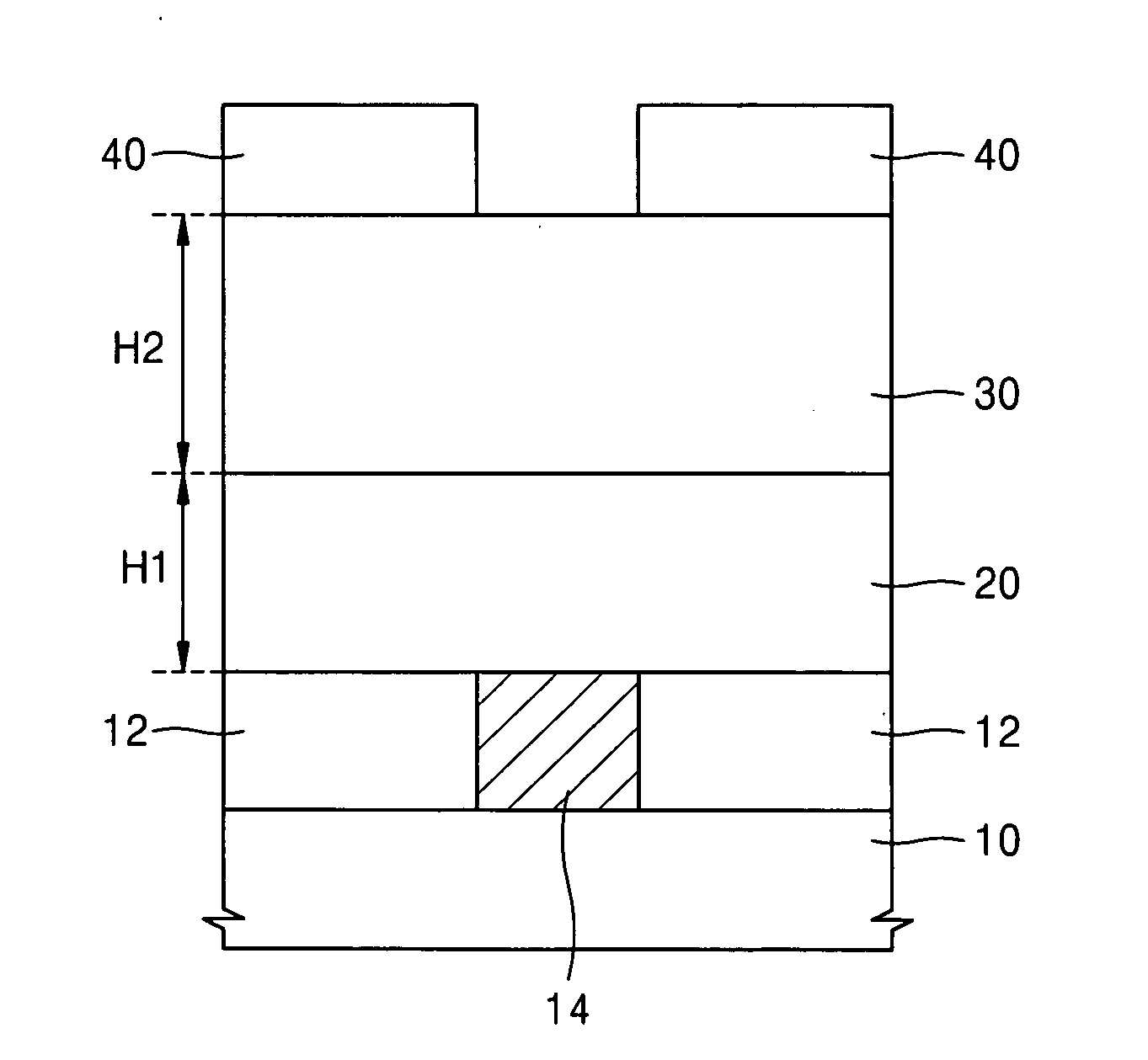
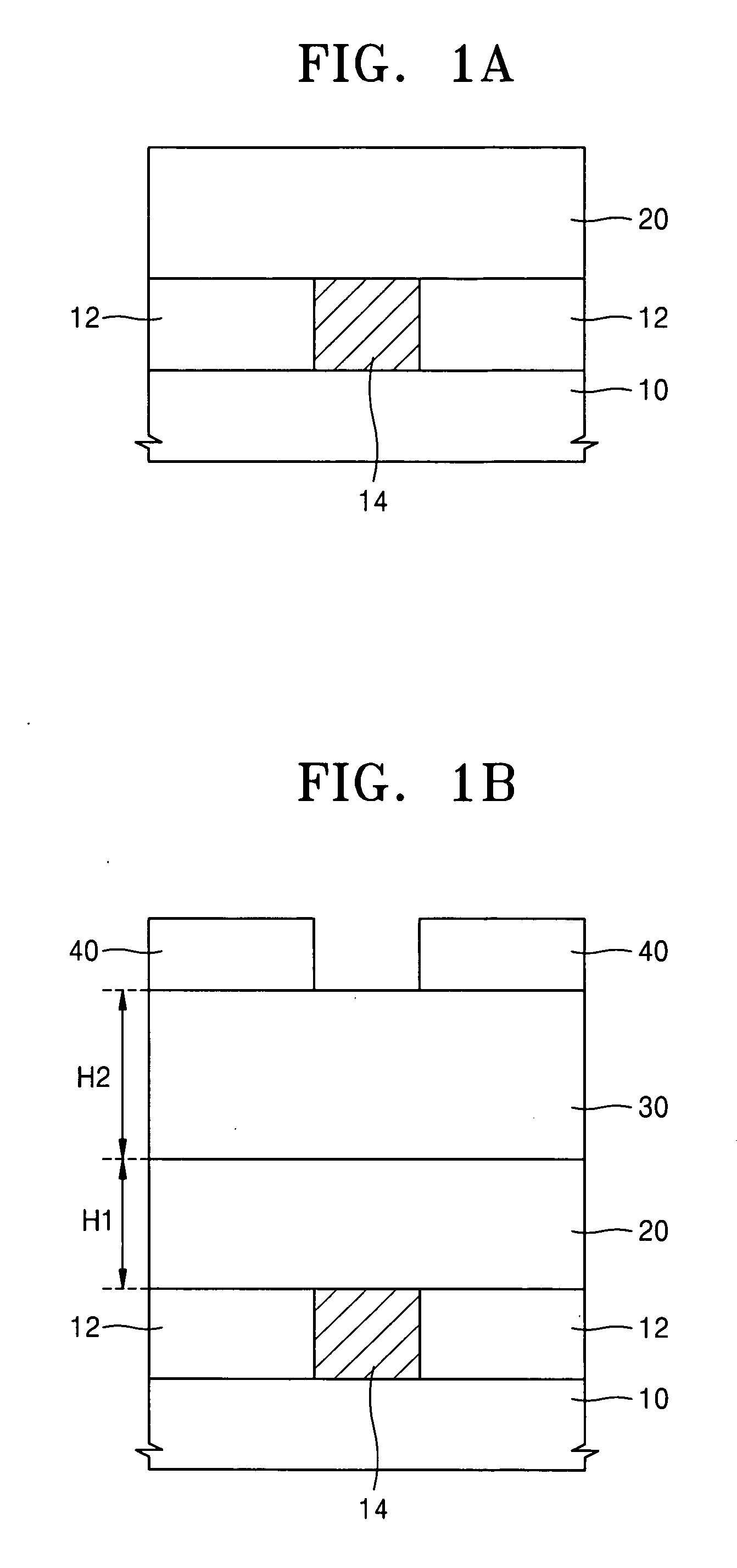
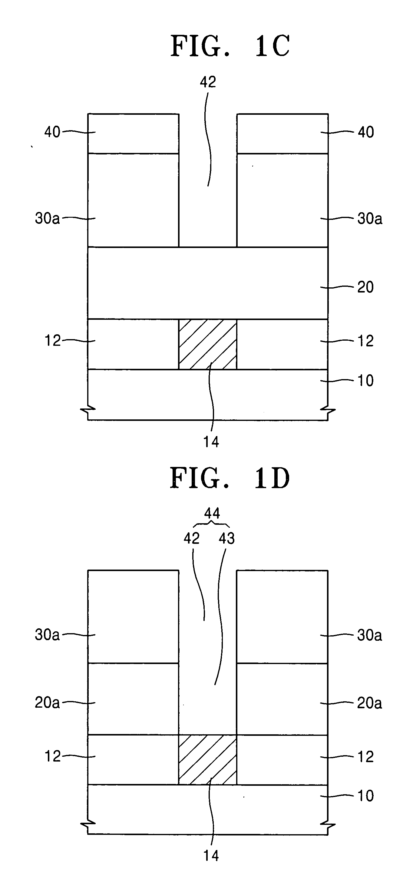
[0033] According to the present invention, a carbon-containing layer pattern is formed with a relatively large height as a lower mold layer in the formation of a bottom electrode of an OCS capacitor. Therefore, a lower structure of the device is not damaged by an etchant during a wet-etch for removing an oxide layer pattern as an upper mold layer, since the penetration length of the etchant down to the lower structure is increased due to the large height of the carbon-containing layer pattern. Further, it is possible to form a storage node hole having a greater outer diameter at a lower portion

Problems solved by technology

However, in the previously-introduced conventional methods of forming the cylindrical-shaped bottom electrode, an etchant may penetrate through the interface between the bottom electrode and the etch stop layer down to a lower structure, thereby causing damage to the lower structure.
However, if the thickness of the etch stop layer is increased when the etch stop layer is formed of the silicon nitride layer, the elements in the upper structure may be broken or damaged during dry-etching of the etch stop layer to form the node hole.
Further, if the thickness of the etch stop layer is increased, a surface area of the bottom electrode is reduced by as much as the area where the outer wall of the bottom electrode contacts the etch stop layer pattern, thereby failing to provide a desired capa

Method used


Image

  • Method of manufacturing a semiconductor memory device
  • Method of manufacturing a semiconductor memory device
  • Method of manufacturing a semiconductor memory device

Examples


Embodiment Construction

[0039] Korean Patent Application No. 2004-47658, filed on Jun. 24, 2004, in the Korean Intellectual Property Office, and entitled: “Method of Manufacturing Semiconductor Memory Device,” is incorporated by reference herein in its entirety.

[0040] The present invention will now be described more fully hereinafter with reference to the accompanying drawings, in which exemplary embodiments of the invention are shown. The invention may, however, be embodied in different forms and should not be construed as limited to the embodiments set forth herein. Rather, these embodiments are provided so that this disclosure will be thorough and complete, and will fully convey the scope of the invention to those skilled in the art. In the figures, the dimensions of films, layers and regions are exaggerated for clarity of illustration. It will also be understood that when a layer is referred to as being “on” another layer or substrate, it can be directly on the other layer or substrate, or intervening...


PUM


Abstract

A method of manufacturing a semiconductor memory device includes forming a carbon-containing layer on a semiconductor substrate, forming an insulating layer pattern on the carbon-containing layer, the insulating layer pattern partially exposing an upper surface of the carbon-containing layer, dry-etching the exposed portion of the carbon-containing layer, to form a carbon-containing layer pattern for defining a storage node hole, forming a bottom electrode inside the storage node hole, forming a dielectric layer on the bottom electrode inside the storage node hole, the dielectric layer covering the bottom electrode, and forming an upper electrode on the dielectric layer inside the storage node hole, the upper electrode covering the dielectric layer.

Description

BACKGROUND OF THE INVENTION [0001] 1. Field of the Invention [0002] The present invention relates to a method of manufacturing a semiconductor memory device. More particularly, the present invention relates to a method of manufacturing a semiconductor memory device having a bottom electrode, which may have a cylindrical-shape, formed in fine cell areas. [0003] 2. Description of the Related Art [0004] With a recent trend of more highly-integrated semiconductor memory devices, a design rule of the memory device is reduced, and an area for a unit memory cell thereof is also reduced. A capacitor used in a memory cell of a dynamic random access memory (DRAM) device is required to have a minimum tolerable capacitance sufficient to provide data input / output characteristics and data reading characteristics even though an area thereof is reduced. The reduction of process margins and areas has significantly affected a design of a memory cell capacitor due to the demand as described above. The...

Claims


Application Information

Patent Timeline
IPC IPC(8): H01L21/02H01L21/8242H01L21/311
CPCH01L21/31116H01L21/31122H01L28/91H01L27/10852H01L21/31138H10B12/033H10B99/00
Inventor CHO, SUNG-ILCHI, KYEONG-KOOCHUNG, SEUNG-PILKANG, CHANG-JINLEE, CHEOL-KYU
Owner SAMSUNG ELECTRONICS CO LTD
Why Eureka
Try Eureka