Pump/motor operating mode switching control for hydraulic hybrid vehicle

a hybrid vehicle and operating mode technology, applied in hybrid vehicles, fluid couplings, free piston pumps, etc., can solve the problems of sudden vehicle movement, vibration of components, and vibration of noise shock waves toward the pump/motor, so as to prevent cavitation, damage hydraulic components, and increase the pressure in the lines and inlet ports relatively slowly

Active Publication Date: 2006-01-05
FORD GLOBAL TECH LLC
View PDF11 Cites 35 Cited by
  • Summary
  • Abstract
  • Description
  • Claims
  • Application Information

AI Technical Summary

Benefits of technology

[0009] High pressure solenoid valves accomplish this switching, which must be done carefully to prevent unsafe or unpleasant conditions for the driver or other vehicle occupants. For example, when switching from pumping to motoring, the valve opens to allow high pressure fluid to go to the inlet port of the pump / motor. There is an immediate rise in pressure in the hydraulic line causing a noisy shock wave to propagate toward the pump / motor that may vibrate the components. In addition, if the pump / motor has a positive, non-zero displacement, the wheels of the vehicle will be driven by torque transmitted from the pump / motor causing the vehicle suddenly, unexpectedly to move.
[0010] To prevent these problems, a proportional valve, whose output is applied to the swashplate of the pump / motor to establish the magnitude of pump / motor displacement, is controlled so that there is no displacement when switching between pumping and motoring. There is a hydraulic circuit leading from the accumulator to the inlet port. This hydraulic circuit has its own solenoid valve and more importantly has a restriction that limits flow. When a switch to motoring occurs, this low flow rate valve is opened first so that the pressure in the lines and on the inlet port rises relatively slowly. After the pressure has risen to a sufficient level, the valve in the main flow path is opened. If, after motoring for a predetermined period, the pressure in the accumulator is not sufficient to provide useful work, the pump / motor is put into a non-motoring mode to prevent cavitation, which is very noisy and can damage hydraulic components. The switching must occur before exhausting accumulator pressure to prevent noise and vibration from being transmitted to the occupants of the vehicle. In this case, the displacement control-proportional valve is ramped down to zero at a controlled rate before the mode control valves are switched.
[0011] A system according to this invention for transmitting power hydraulically to and from the wheels of a motor vehicle includes an accumulator containing fluid at relatively high pressure, a reservoir containing fluid at lower pressure, and a pump / motor driveably connected to the wheels and having an inlet, an outlet, and a variable volumetric displacement for pumping fluid between the accumulator and the reservoir. A first circuit connects the inlet to the reservoir and the outlet to the accumulator. A second circuit, which connects the inlet to the accumulator and the outlet to the reservoir, includes a first path having a low flow rate capacity and a second path having a higher flow rate capacity. A controller switches between pumping operation and motoring operation, opens and closes the first path during motoring operation, and reduces the displacement before switching between pumping operation and motoring operation. The first path includes a first valve responsive to the controller for opening and closing a connection between the accumulator and the inlet, and a first orifice arranged in series with the first valve having a relatively low flow rate capacity. The second path, arranged in parallel with the first path between the accumulator and the inlet, includes a second valve responsive to the controller for opening and closing a connection between the accumulator and the inlet, and a second orifice arranged in series with the second valve having a higher flow rate capacity than that of the first orifice.
[0012] The system switches operation of a hydraulic drive system for a vehicle between pumping and motoring by determining whether the pump / motor should enter pumping operation or motoring operation, alternately entering and exiting pumping operation and motoring operation, controlling the volumetric displacement during pumping operation and motoring operation, and decreasing the volumetric displacement to substantially zero displacement before exiting pumping operation and motoring operation.

Problems solved by technology

There is an immediate rise in pressure in the hydraulic line causing a noisy shock wave to propagate toward the pump / motor that may vibrate the components.
In addition, if the pump / motor has a positive, non-zero displacement, the wheels of the vehicle will be driven by torque transmitted from the pump / motor causing the vehicle suddenly, unexpectedly to move.
If, after motoring for a predetermined period, the pressure in the accumulator is not sufficient to provide useful work, the pump / motor is put into a non-motoring mode to prevent cavitation, which is very noisy and can damage hydraulic components.

Method used


Image

  • Pump/motor operating mode switching control for hydraulic hybrid vehicle
  • Pump/motor operating mode switching control for hydraulic hybrid vehicle
  • Pump/motor operating mode switching control for hydraulic hybrid vehicle

Examples


Embodiment Construction

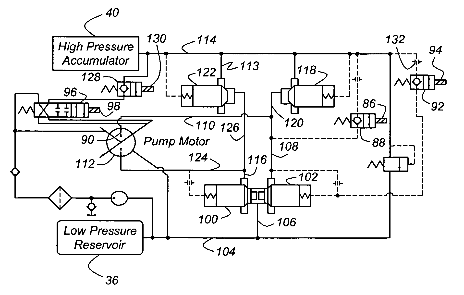
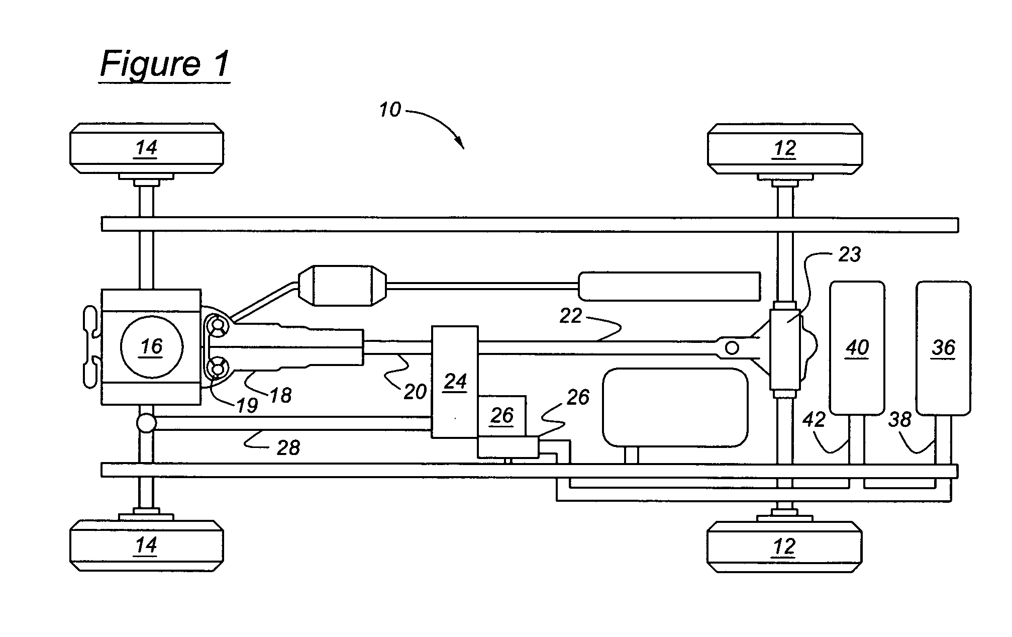
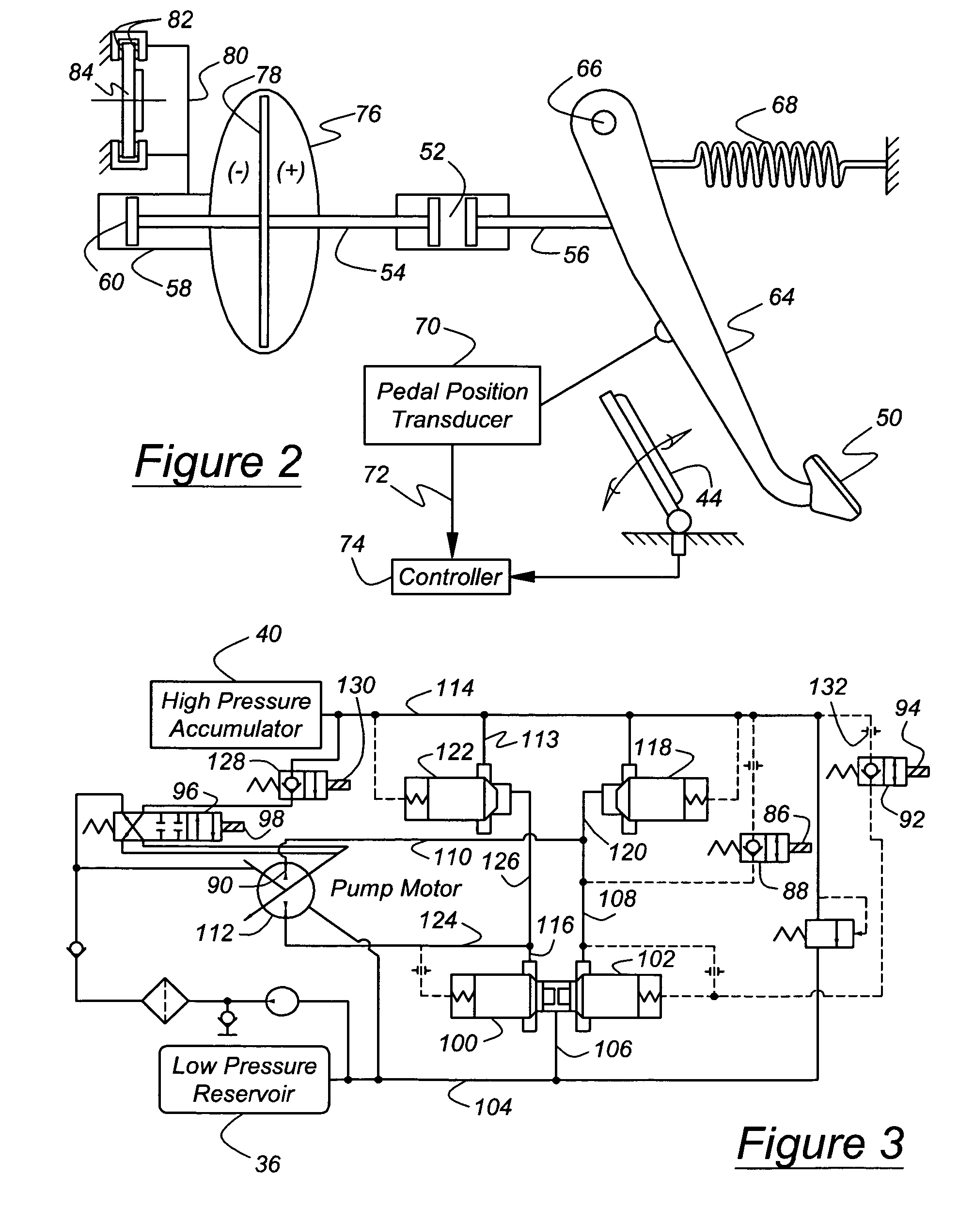
[0019] Referring now to the drawings, there is illustrated in FIG. 1 a hydraulic hybrid powertrain 10 for driving the rear wheels 12 and front wheels 14 of a motor vehicle. A power source 16, such as an internal combustion engine, is driveably connected to a transmission 18, preferably an automatic transmission that produces multiple ratios of the speed of the engine and the speed of an output shaft 20. Suitable alternative transmissions include those that are manually operated, and those that produce continuously variable speed ratios or infinitely variable speed ratios, having chain drive, belt drive or traction drive mechanisms. The transmission output shaft 20 is continually driveably connected to the rear wheels 12 through a rear driveshaft 22, rear axle shafts, and a rear differential mechanism. A transfer case 24 selectively transfers a portion of the torque carried by output shaft 20 to a front driveshaft 28, which is driveably connected to the front wheels 14 through a fron...


PUM


Abstract

A system according to this invention for transmitting power hydraulically to and from the wheels of a motor vehicle includes an accumulator containing fluid at relatively high pressure, a reservoir containing fluid at lower pressure, and a pump/motor driveably connected to the wheels and having an inlet, an outlet, and a variable volumetric displacement for pumping fluid between the accumulator and the reservoir. A first circuit connects the inlet to the reservoir and the outlet to the accumulator. A second circuit, which connects the inlet to the accumulator and the outlet to the reservoir, includes a first path having a low flow rate capacity, a second path having a higher flow rate capacity. A controller switches between pumping operation and motoring operation, opens and closes the first path during motoring operation, and reduces the displacement before switching between pumping operation and motoring operation. The first path includes a first valve responsive to the controller for opening and closing a connection between the accumulator and the inlet, and a first orifice arranged in series with the first valve having a relatively low flow rate capacity. The second path, arranged in parallel with the first path between the accumulator and the inlet, includes a second valve responsive to the controller for opening and closing a connection between the accumulator and the inlet, and a second orifice arranged in series with the second valve having a higher flow rate capacity than that of the first orifice.

Description

BACKGROUND OF THE INVENTION [0001] The invention relates to a hybrid vehicle powertrain having an engine and a hydraulic drive. More particularly, the invention pertains to switching a pump / motor between pumping operation and motoring operation. [0002] Hydraulic Power Assist (HPA) is a type of hydraulic hybrid vehicle, in which energy from regenerative braking or from an engine is stored in a hydro-pneumatic accumulator, and the conversion between mechanical power and hydraulic power is achieved through high pressure pump / motor having a variable volumetric displacement. In an HPA system, using stored energy from regenerative braking to help accelerate the vehicle reduces the burden on the engine and reduces fuel use. [0003] Because of the high power density available with such hydraulic systems, it is possible to recover efficiently a significant portion of braking energy with an HPA system comprised of a single pump / motor and storage accumulators. With a 7000 lb. vehicle and a pump...

Claims


Application Information

Patent Timeline
Patent Type & Authority Applications(United States)
IPC IPC(8): F04B31/00B60K6/12B60T1/10F04B49/03
CPCB60K6/12B60T1/10Y02T10/6208F04B49/03B60W2540/12Y02T10/62F04B39/00
Inventor TESLAK, CHRISKEPNER, RONCHALK, PETERTANG, CHUANCHICARLSON, CLIFF
Owner FORD GLOBAL TECH LLC
Why Eureka
Try Eureka